.jpg)
NDT Calibration Reference Standards.
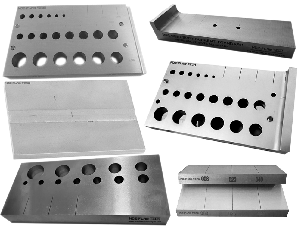
Eddy Current Testing Calibration/Reference Standard
Eddy Current Testing Calibration/Reference Standard Eddy current testing is one of several non-destructive testing methods that use the electromagnetism principle for flaw detection in conductive materials. A specially designed coil energized with an alternating-current is placed in proximity to the test surface, generating a changing magnetic field that interacts with the test-part and produces eddy currents in the vicinity. Variations in the changing phases and magnitude of these eddy currents are then monitored through the use of a receiver-coil or by measuring changes to the alternate current flowing in the primary excitation-coil. The electrical conductivity variations, the magnetic permeability of the test-part, or the presence of any discontinuities, will cause a change in the eddy current and a corresponding change in phases and amplitude of the measured current. The changes are shown on a screen and are interpreted to identify defects. NDE FLAW TECHNOLOGIES PVT. LTD. are the manufacturer of standard blocks for Eddy Current Testing (ECT) according to the standards and codes.
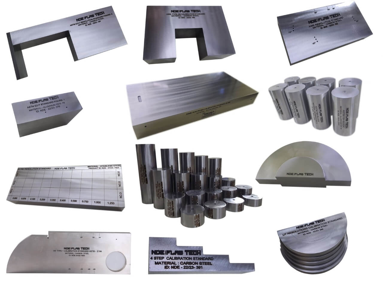
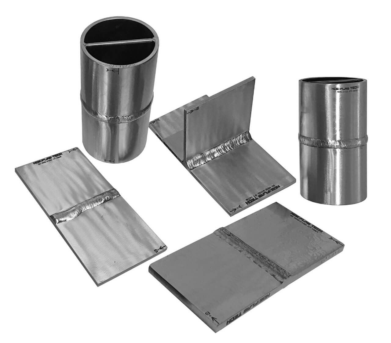
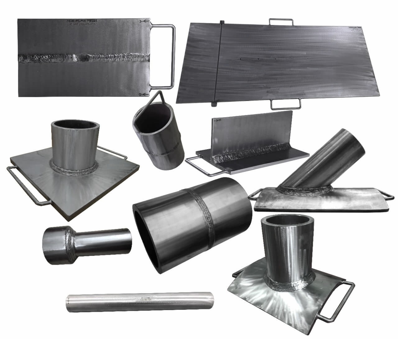
Ultrasonic Testing Calibration/Reference Standard
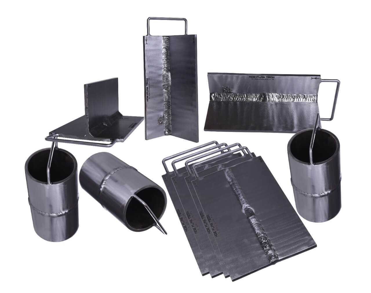
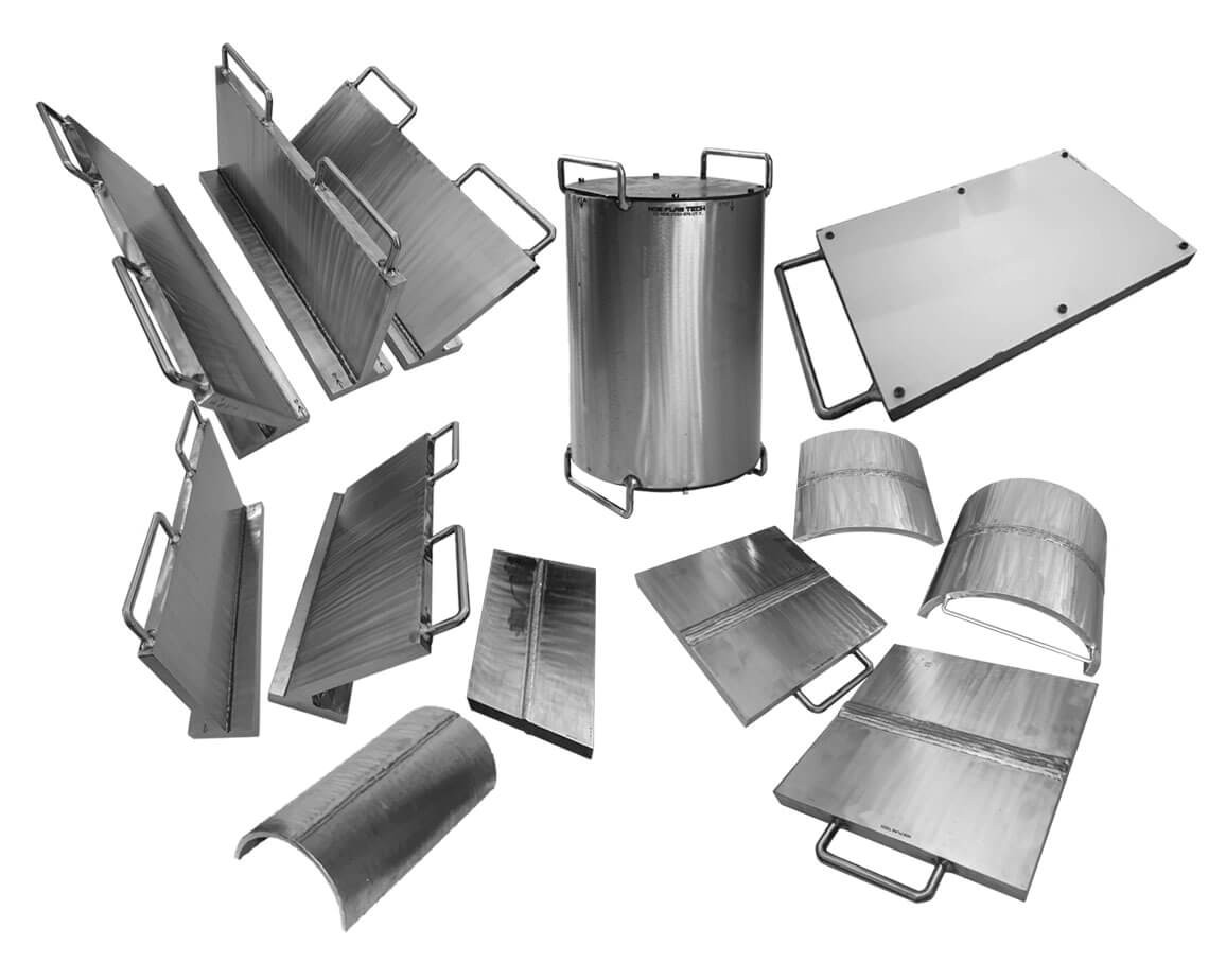
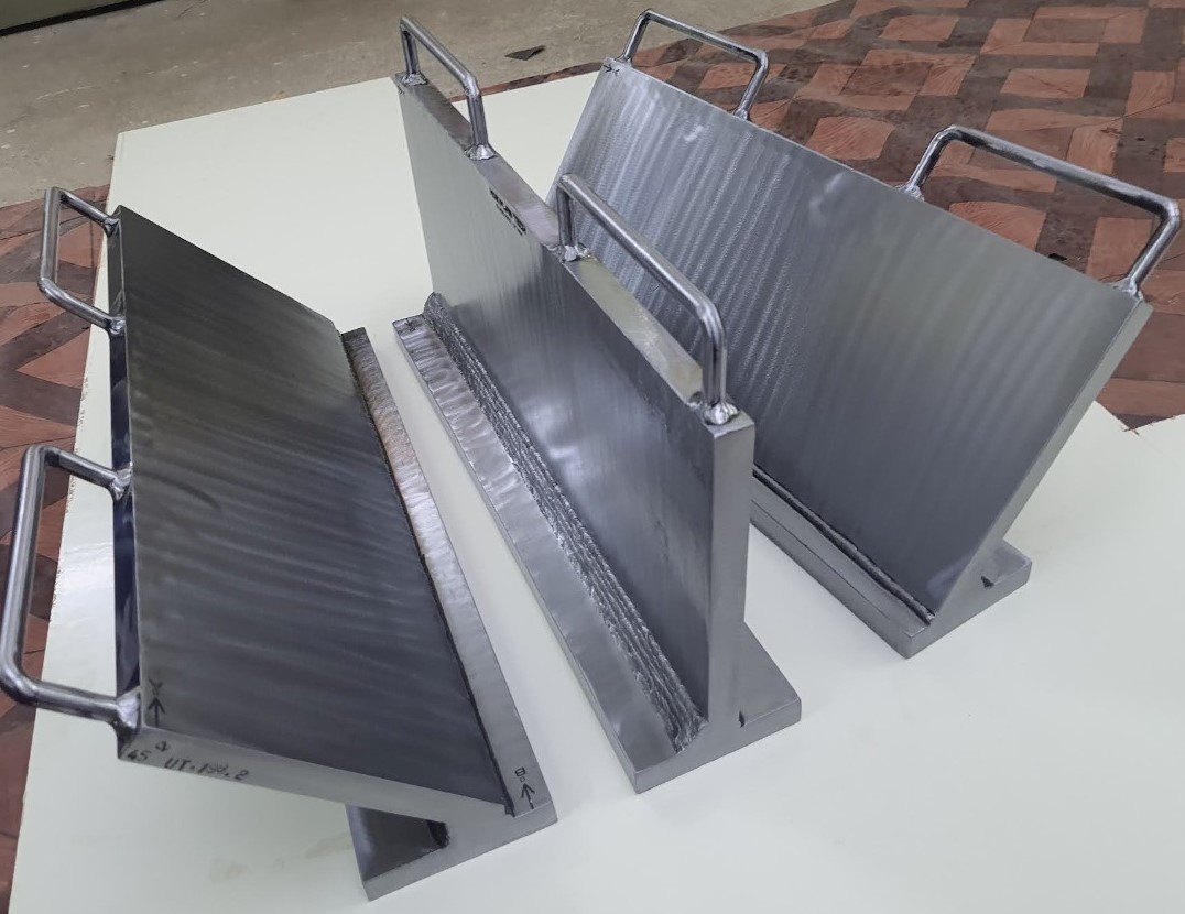
Ultrasonic Testing Calibration/Reference Standard Ultrasonic testing (UT) comprises a range of non-destructive testing (NDT) techniques that send ultrasonic waves through an object or material. These high frequency sound waves are transmitted into materials to characterize the material or for flaw detecting. Most UT inspection applications use short pulse waves with frequencies ranging from 0.1-15 MHz, although frequencies up to 50 MHz can be used. One common application for this test method is ultrasonic thickness measurement, which is used to ascertain the thickness of an object such as when assessing pipework corrosion. Ultrasonic inspection uses a piezoelectric transducer connected to a flaw detector, which in its most basic form is a pulser-receiver and oscilloscope display. The transducer is passed over the object being inspected, which is typically coupled to the test object by gel, oil or water. This couplant is required to efficiently transmit the sound energy from the transducer into the part, however this couplant is not required when performing tests with non-contact techniques such as electromagnetic acoustic transducer (EMAT) or by laser excitation. According to Ultrasonic Testing (UT) principle NDE FLAW TECHNOLOGIES PVT. LTD. well export of making artificial flaws over subsurface in the test specimen also we are a manufacturer of calibration block according to the standards.
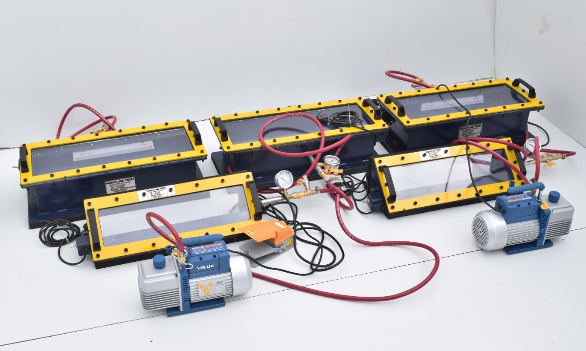
Dye Penetrant Testing Calibration/Reference Standard
Dye Penetrant Testing (DPT) / Penetrant Testing (PT) / Liquid Penetrant Testing (LPT) processes are non-destructive testing methods based on the capillary action at defects which for detecting discontinuities that are open to surface. They may be effectively used in the inspection of both ferrous and non-ferrous metals and on non-porous, non-metallic materials, such as ceramics, plastics and glass. Surface discontinuities, such as cracks, seams, laps, cold shuts and laminations are indicated by these methods. Flaw detection with the help of liquid penetrant is being increasingly used in various industries in the country and recommendations of a general character providing guidance on the applications of these methods are considered necessary. According to Dye Penetrant Testing (DPT) / Penetrant Testing (PT) / Liquid Penetrant Testing (LPT) principle NDE FLAW TECHNOLOGIES PVT. LTD. well export of making artificial flaws in both surface and near surface in the test specimen also we are a manufacturer of calibration block according to the standards.
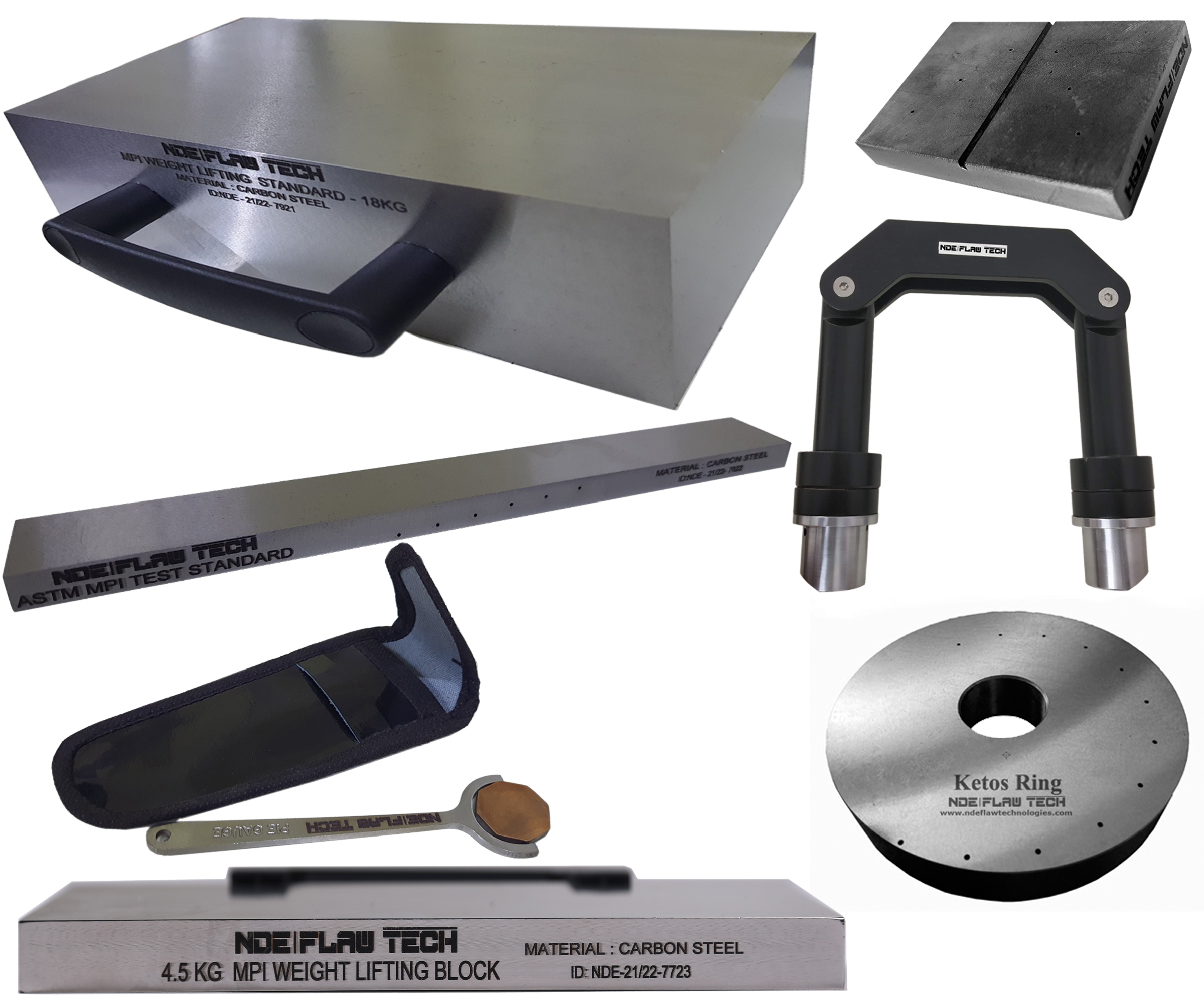
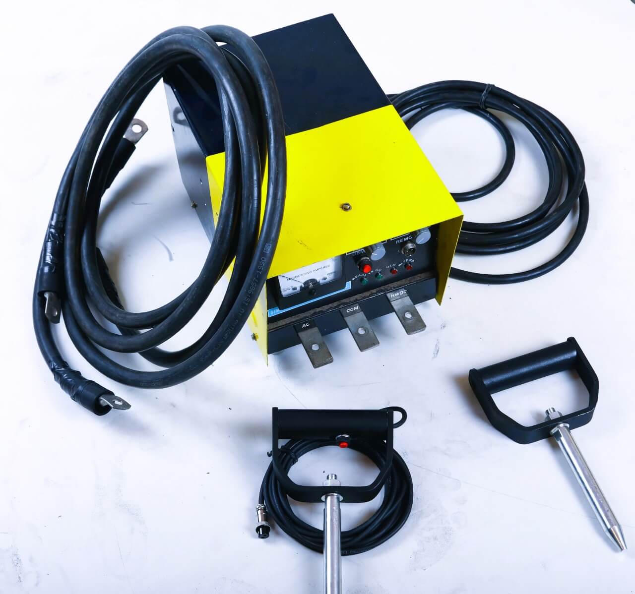
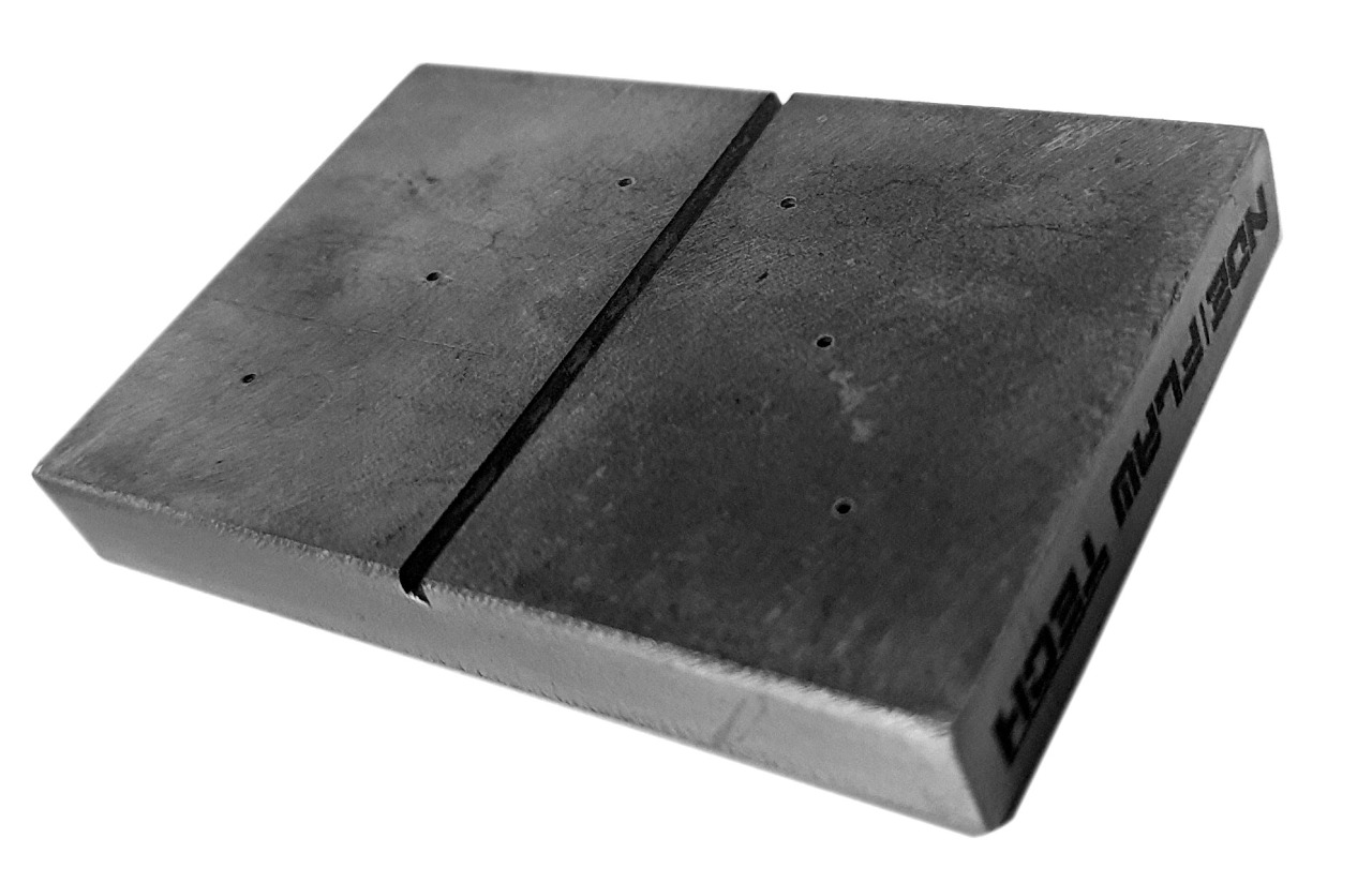
Magnetic Particle Testing Calibration/Reference Standard
Magnetic Particle Testing Calibration/Reference Standard This method is used for the detection of surface and near-surface flaws in ferromagnetic materials and is primarily used for crack detection. The specimen is magnetized either locally or overall, and if the material is sound the magnetic flux is predominantly inside the material. If, however, there is a surface-breaking flaw, the magnetic field is distorted, causing local magnetic flux leakage around the flaw. This leakage flux is displayed by covering the surface with very fine iron particles applied either dry or suspended in a liquid. The particles accumulate at the regions of flux leakage, producing a build-up which can be seen visually even when the crack opening is very narrow. Thus, a crack is indicated as a line of iron powder particles on the surface. The method is applicable to all metals which can be strongly magnetized – ferritic steels and irons, but not generally austenitic steels. The method of magnetization must produce a magnetic field with lines of force at a large angle to the expected direction of the cracks to be detected, so that it is usual to apply the magnetization more than once in different directions, for example in two directions mutually at right-angles, but methods of swinging the field direction during magnetization are available. According to MPI/MPT principle NDE FLAW TECHNOLOGIES PVT. LTD. well export of making artificial flaws in both surface and near surface in the test specimen also we are a manufacturer of calibration block according to the standards.
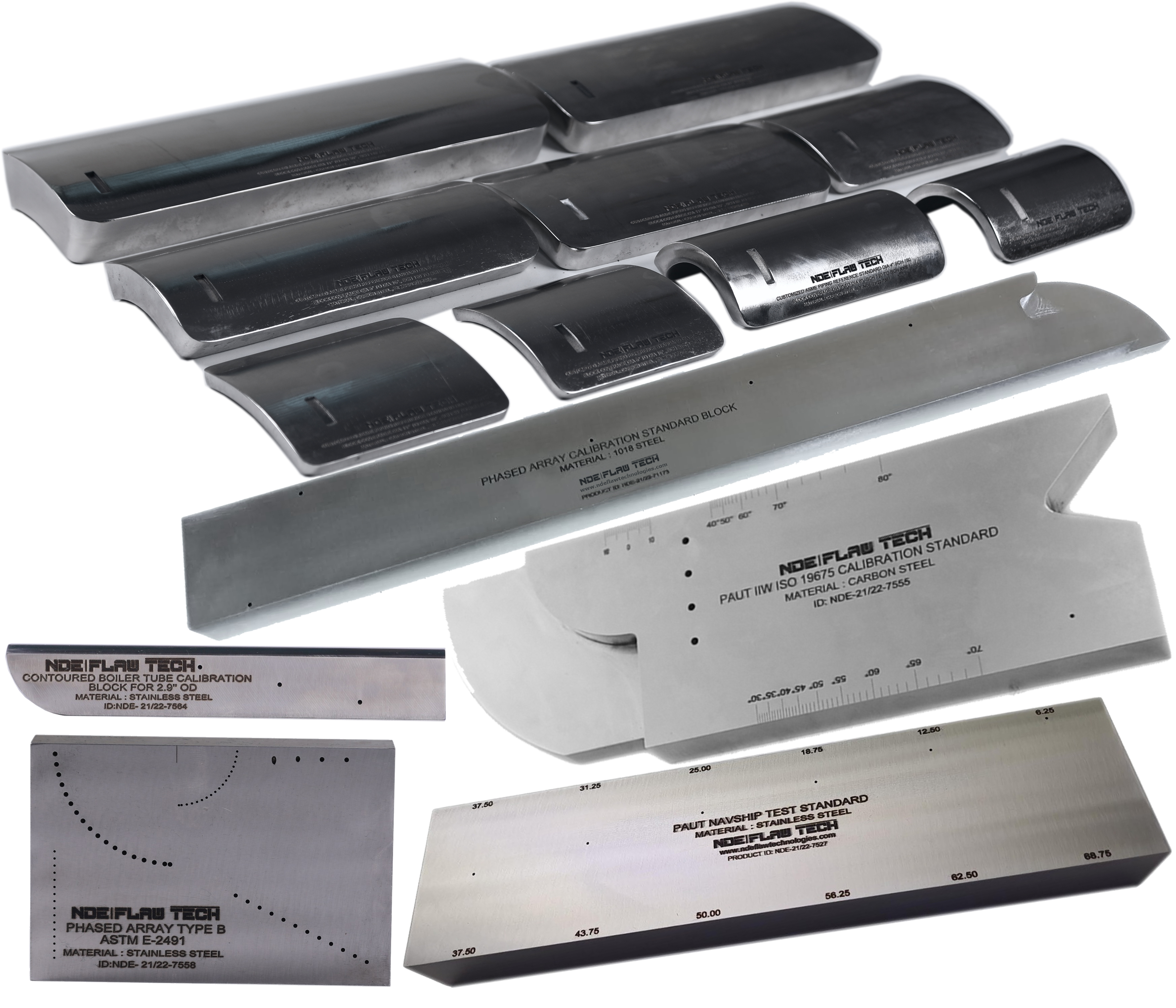
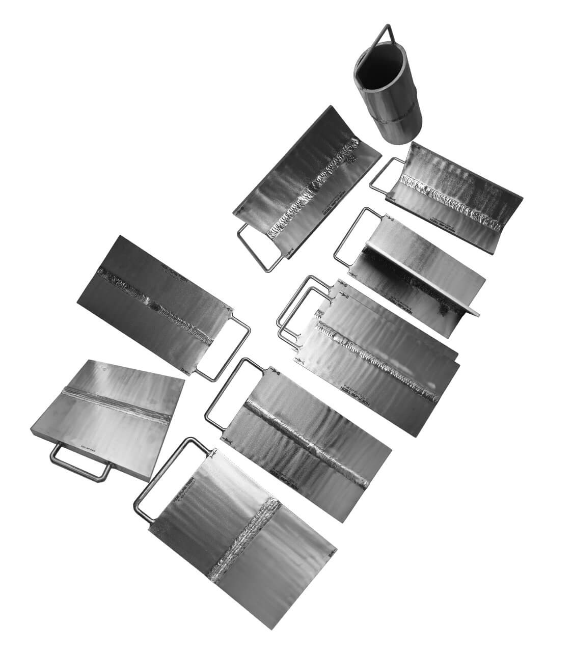
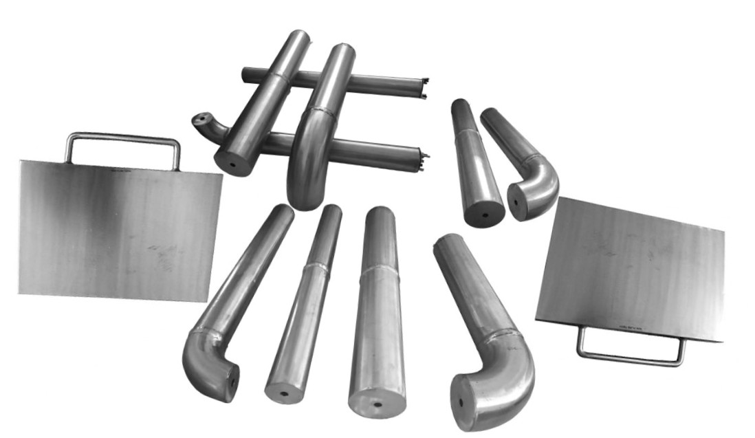
PAUT and TOFD Calibration/Reference Standard
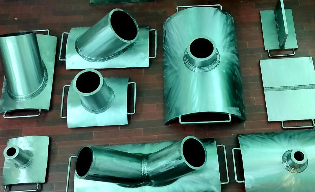
PAUT and TOFD Calibration/Reference Standard Phased Array Ultrasonic Testing (PAUT), also known as phased array UT, is an advanced non-destructive inspection technique that uses a set of ultrasonic testing (UT) probes made up of numerous small elements. Each of these is pulsed individually with computer-calculated timing to create the phased aspect of the process, while the array refers to the multiple elements that make up a PAUT system. The beam from a phased array probe can be focused and electronically swept across an inspection piece without moving the probe itself. This differs from single element probes (also known as monolithic probes). These more conventional probes need to be physically moved or turned to cover larger areas, which is not required for PAUT. Phased array ultrasonic testing is based on the principles of wave physics, which also have applications in areas including optics and electromagnetic antennae. In time-of-flight diffraction (ToFD) systems, a pair of ultrasonic probes is used, sitting on opposite sides of a weld-joint or area of interest. A transmitter probe emits an ultrasonic pulse which is picked up by the receiver probe on the opposite side. In an undamaged part, the signals picked up by the receiver probe are from two waves: one that travels along the surface (lateral wave) and one that reflects off the far wall (back-wall reflection). When a discontinuity such as a crack is present, there is a diffraction of the ultrasonic sound wave from the top and bottom tips of the crack. Using the measured time of flight of the pulse, the depth of the crack tips can be calculated automatically by trigonometry application. This method is even more reliable than traditional radiographic, pulse echo manual UT and automated UT weld testing methods. ToFD offers great accuracy for measuring the critical through-wall size of crack-like-defects. The accuracy of greater than ±1mm can be obtained in a wide range of material thickness from which pressurised components are constructed. ToFD was initially developed as a method of accurate monitoring and sizing of through-wall height of in-service discontinuities in the nuclear industry. It has now been independently validated as one of the most effective techniques for locating and sizing discontinuities in ferritic welds. NDE FLAW TECHNOLOGIES PVT. LTD. are the manufacturer of standard blocks for Phased Array Ultrasonic Testing (PAUT) and Time of Flight Diffraction (ToFD).
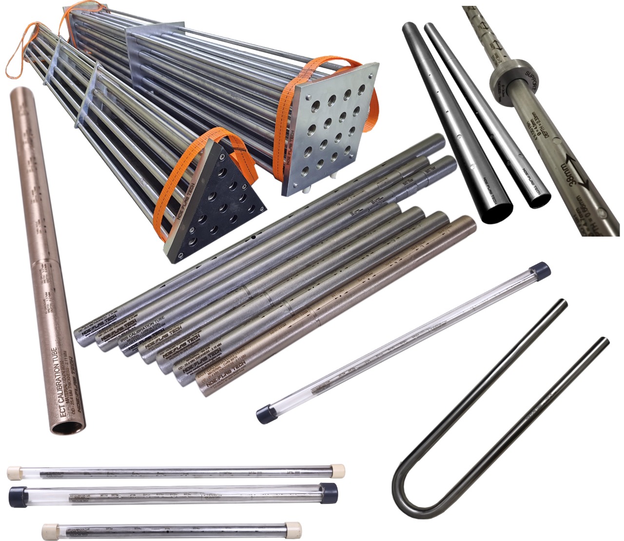
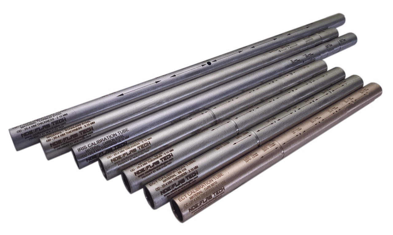
Eddy Current Tube Calibration/Reference Standard
Eddy current testing of tubes is an effective way of assessing the condition and lifespan of tubes, particularly in the power generation, petrochemical, chemical, fertilizer and air conditioning industries. The technique is applied to detect corrosion, pitting, cracks, erosion and other changes to both the tube’s interior and exterior surfaces. It is a high-speed inspection method and one of the major advantages is that it can be performed through paint and coatings. The technique is only suitable for non-ferrous material such as stainless steel, copper and titanium. We also perform remote field and magnetic biased eddy current testing on carbon tubing. Eddy current testing uses electromagnetic induction to identify defects in tubing. A probe is inserted into the tube and pushed through the entire length of the tube. Eddy currents are generated by the electromagnetic coils in the probe and monitored simultaneously by measuring probe electrical impedance. The information revealed by the probe will detail the tube defects. The scanning data will be recorded by the software and kept us as a backup for future reference. A benefit of eddy current testing is that detection of defects is instant, and can be reported immediately to site or operation managers. Standard calibration tubes are manufactured by NDE FLAW TECHNOLOGIES PVT. LTD. with artificial flaw for calibrating the equipment.
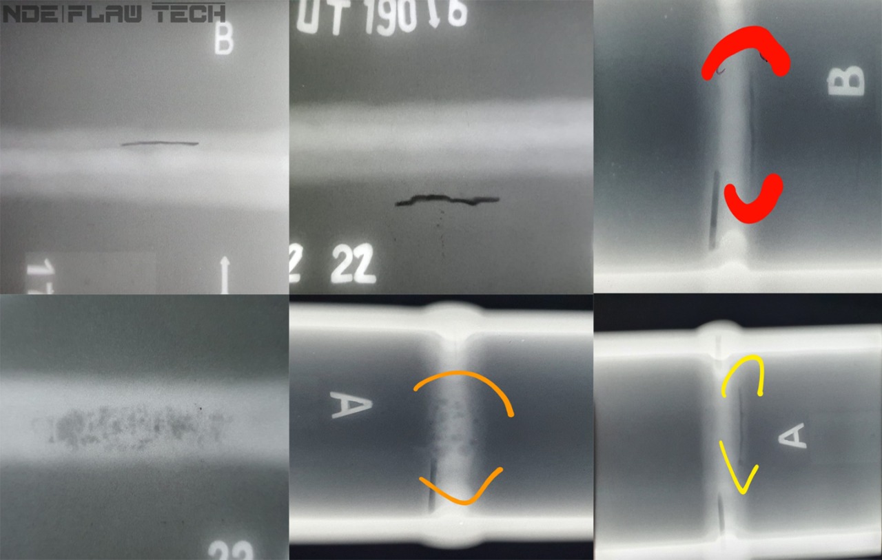
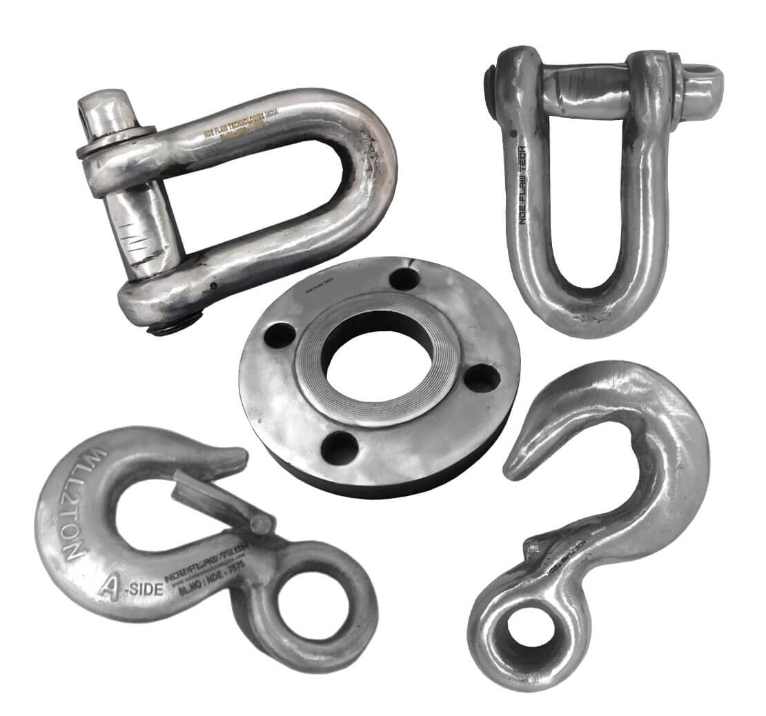
Radiography Testing Calibration/Reference Standard
Radiography Testing Calibration/Reference Standard Radiographic Testing (RT) is a non-destructive testing (NDT) method which uses either x-rays or gamma rays to examine the internal structure of manufactured components identifying any flaws or defects. In Radiography Testing the test-part is placed between the radiation source and film (or detector). The material density and thickness differences of the test-part will attenuate (i.e. reduce) the penetrating radiation through interaction processes involving scattering and/or absorption. The differences in absorption are then recorded on film(s) or through an electronic means. In industrial radiography there are several imaging methods available, techniques to display the final image, i.e. Film Radiography, Real Time Radiography (RTR), Computed Tomography (CT), Digital Radiography (DR), and Computed Radiography (CR). There are two different radioactive sources available for industrial use; X-ray and Gamma-ray. These radiation sources use higher energy level, i.e. shorter wavelength, versions of the electromagnetic waves. Because of the radioactivity involved in radiography testing, it is of paramount importance to ensure that the Local Rules is strictly adhered during operation. Computed Tomography (CT) is one of the lab based advanced NDT methods. CT is a radiographic based technique that provides both cross-sectional and 3D volume images of the object under inspection. These images allow the internal structure of the test object to be inspected without the inherent superimposition associated with 2D radiography. This feature allows detailed analysis of the internal structure of a wide range of components. Standard calibration blocks are manufactured by NDE FLAW TECHNOLOGIES PVT. LTD. with artificial flaw for calibrating the equipment.
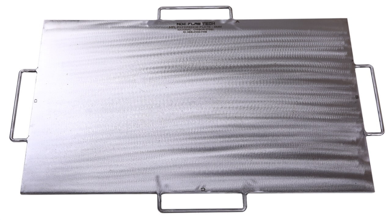
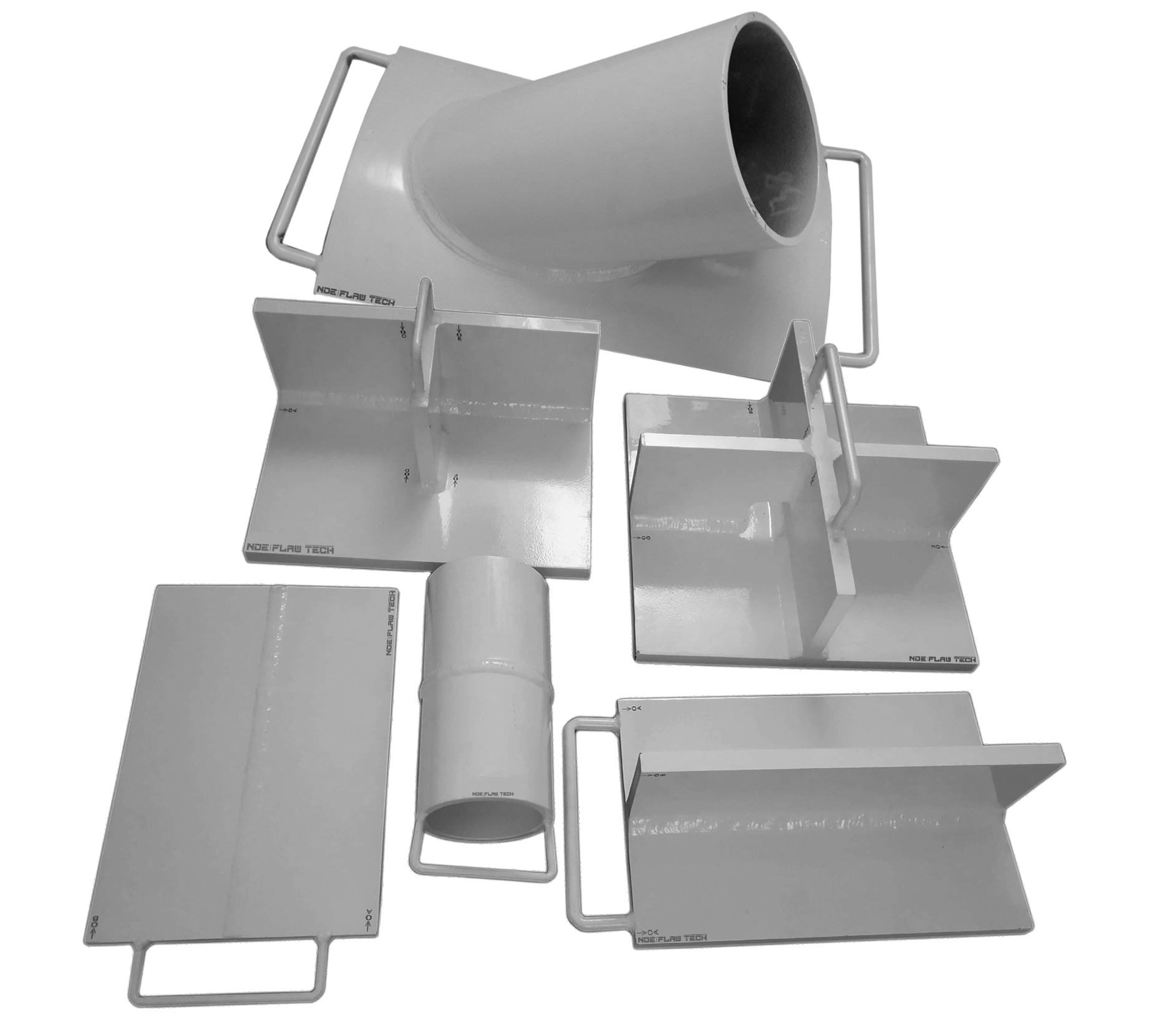
MFL Floor Mapping Calibration/Reference Standard
MFL Floor Mapping Calibration/Reference Standard Magnetic flux leakage (MFL) is a magnetic method of non-destructive testing that is used to detect corrosion, pitting and wall loss in steel structures. Magnetic flux leakage (MFL) is commonly used for inspecting tank floors in the petrochemical industry. Corrosion of the tank floor can lead to the loss of product and cause damage to the environment. Therefore, it is vital that tank floor inspections are carried out in order to prevent the occurrence of such problems. MFL provides a cost-effective and high-speed inspection of tank floors. The method uses permanent or electromagnets to magnetize the tank floor and the resulting magnetic field changes are recorded and analyzed. If there is corrosion, pitting or wall loss, the magnetic field ‘leaks’ and the ‘leakage’ is analyzed to determine the location and severity of the defect of the tank floor – both near and far surface. A map of the corroded areas is provided with the MFL method and this essential data can be stored for future reference and planning. Standard calibration blocks are manufactured by NDE FLAW TECHNOLOGIES PVT. LTD. with artificial flaw also we are to work for customized blocks which recommended by client for calibrating the equipment.
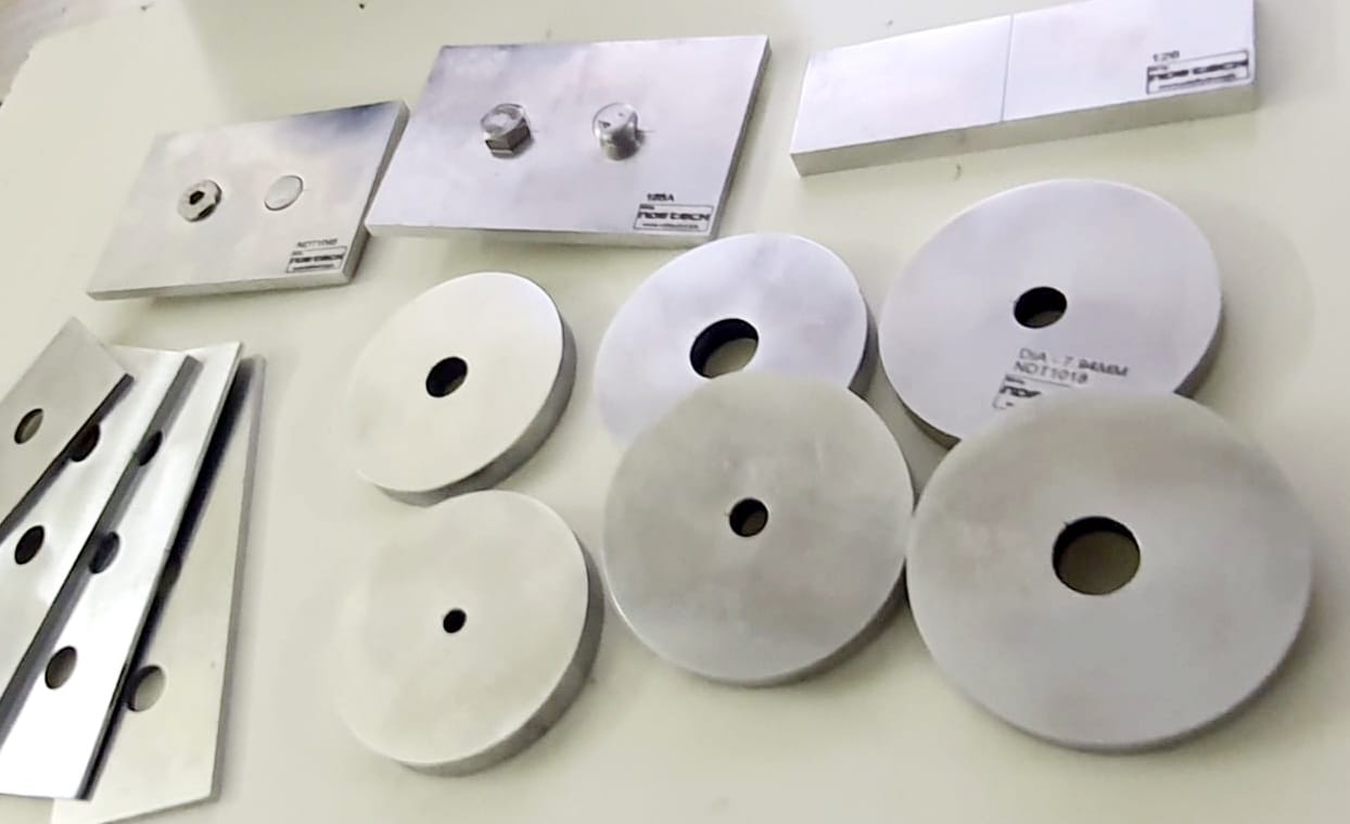
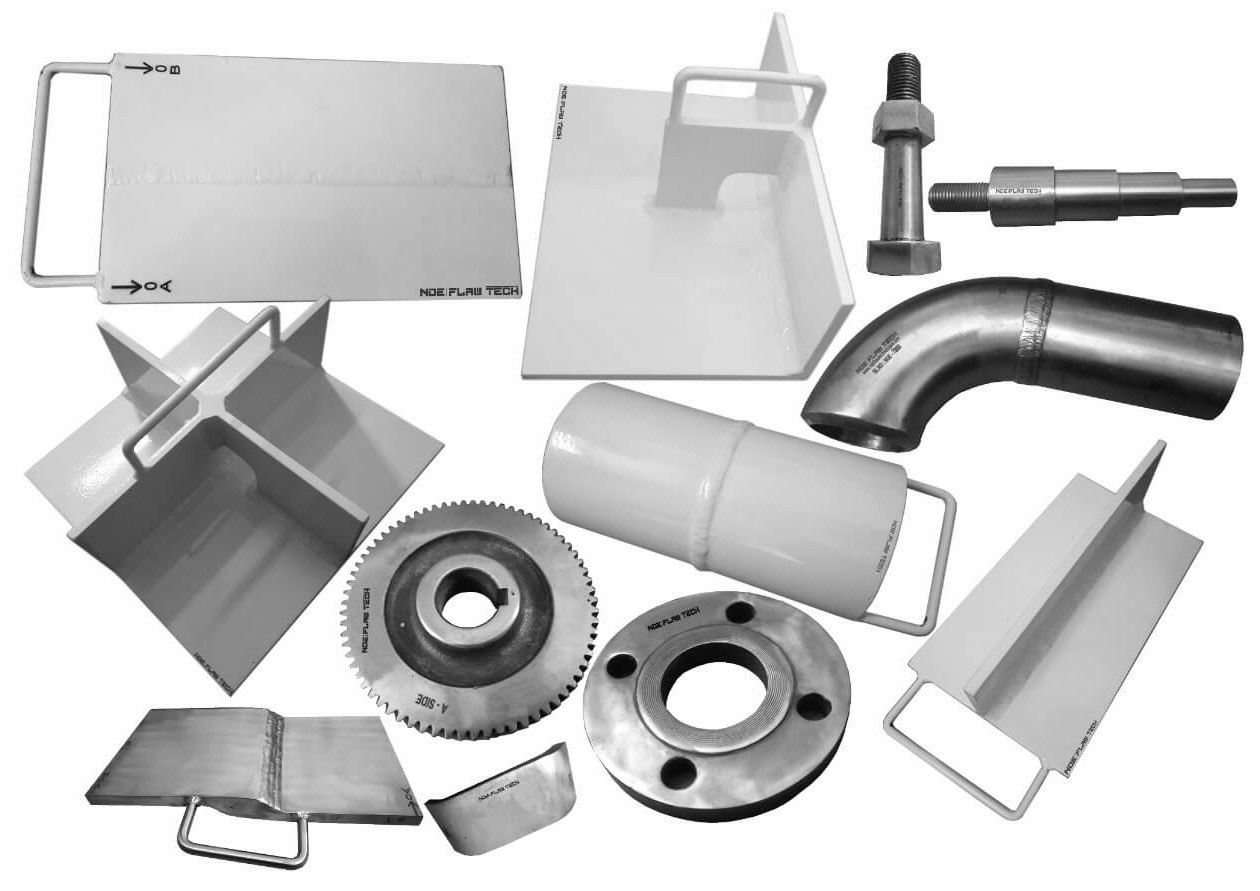
Aerospace Standard Calibration/Reference Standard
Aerospace Standard Calibration/Reference Standard Due to the intricacies of the industry, the aerospace sector has its own NDT qualifications. Your training would be classroom-based and cover both theory and practical elements across five main disciplines. These disciplines include liquid penetrant and magnetic particle testing of products, radiographic testing of welds, eddy current, as well as the ultrasonic and radiographic testing of materials, components and structures. Although there is no level 1 qualification within the aerospace sector. In Aerospace industry they are lot of critical standard blocks recommended by their own NDT manual. FLAW TECHNOLOGIES PVT LTD manufacturing according to aerospace NDT manual, calibration blocks which recommended by client we are manufactured with zero tolerance in the market.