Inch Version
ASME Sec V Basic Calibration Block (½ WITH NOTCH INCH VERSION)
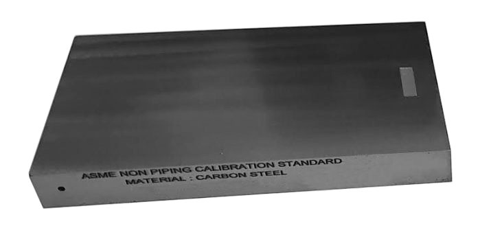
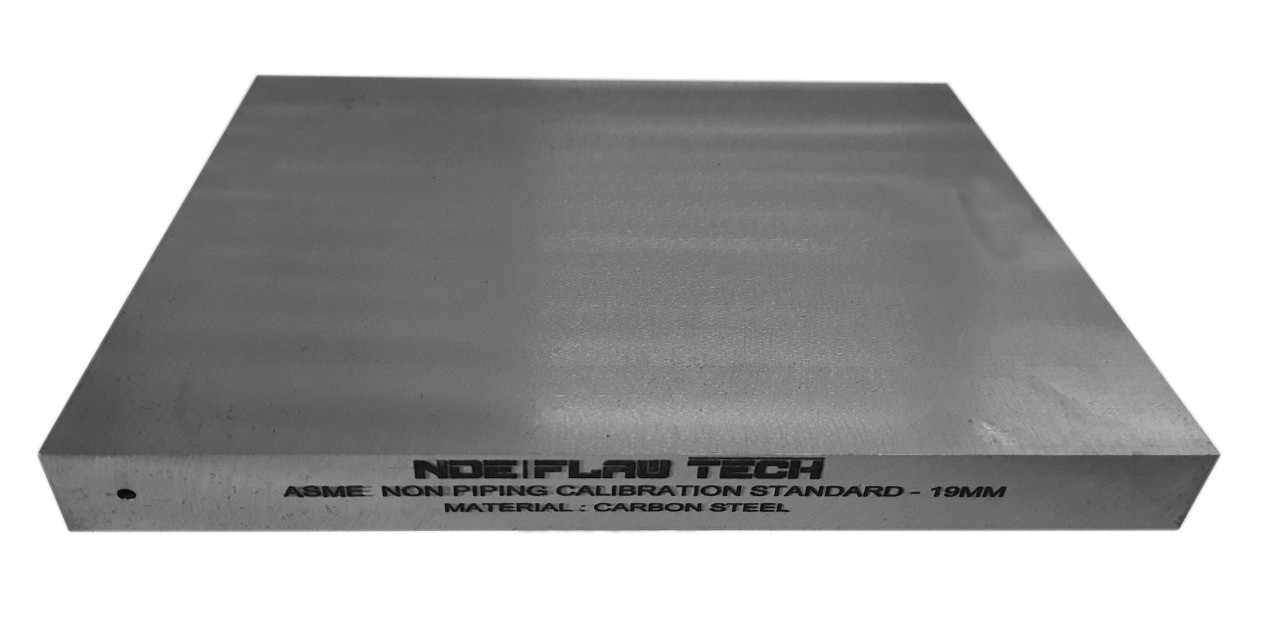
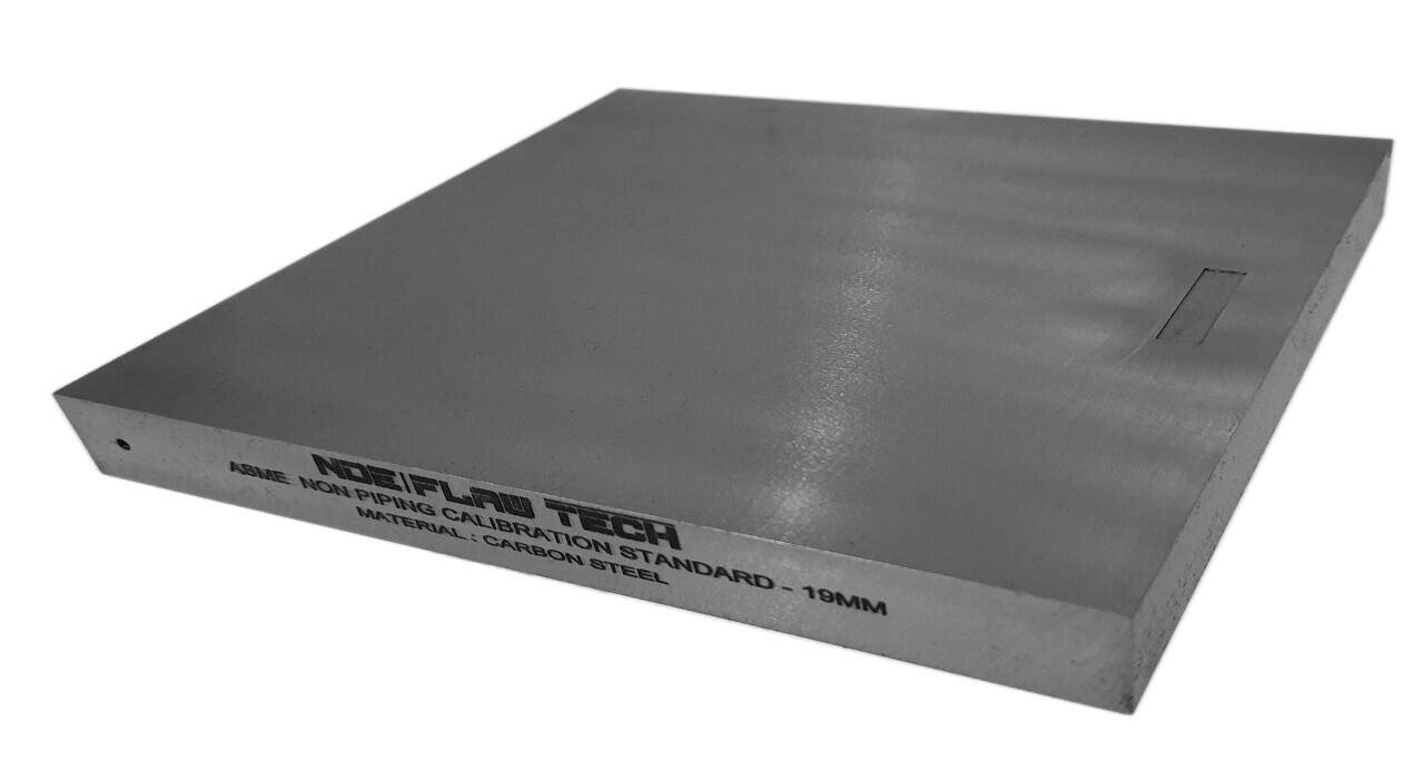
ASME Sec V Basic Calibration Block (½" WITH NOTCH) INCH VERSION This block can be used as a calibration block with a compression probe; however, its main use is as a reference block with either compression or shear wave probes. Its most common uses are for setting test sensitivity prior to inspection, using various depth of individual Side Drilled Holes (SDH) as reference reflectors. The test sensitivity as set by means of Distance amplitude Curve (DAC)/Time Correction Gain (TCG). The block size and reflector locations shall be adequate to perform calibrations for the beam angle(s) and distance range(s) to be used. The block thickness (T) shall be varying according to test object. Acoustic signals from the same reflecting surface will have different amplitudes at different distances from the transducer. Distance amplitude correction (DAC) provides a means of establishing a graphic ‘reference level sensitivity’ as a function of sweep distance on the A-scan display. The use of DAC allows signals reflected from similar discontinuities to be evaluated where signal attenuation as a function of depth has been correlated. Most often DAC will allow for loss in amplitude over material depth (time), graphically on the A-scan display but can also be done electronically by certain instruments. Because near field length and beam spread vary according to transducer size and frequency, and materials vary in attenuation and velocity, a DAC curve must be established for each different situation. DAC may be employed in both longitudinal and shear modes of operation as well as either contact or immersion inspection techniques. A distance amplitude correction curve is constructed from the peak amplitude responses from reflectors of equal area at different distances in the same material. A-scan echoes are displayed at their non-electronically compensated height and the peak amplitude of each signal is marked on the flaw detector screen or, preferably, on a transparent plastic sheet attached to the screen. Reference standards which incorporate side drilled holes (SDH), flat bottom holes (FBH), or notches whereby the reflectors are located at varying depths are commonly used. It is important to recognize that regardless of the type of reflector used, the size and shape of the reflector must be constant. Commercially available reference standards for constructing DAC include ASTM Distance/Area Amplitude and ASTM E1158 Distance Amplitude blocks, NAVSHIPS Test block, and ASME Basic Calibration Blocks Geometry: contains three side-drilled holes at 1.5" deep minimum at 3/32" diameter. Hole locations through the thickness are ½T. Also contains two EDM notches measuring 2%T deep x 1/4" max wide x 1.0" long min. In accordance with ASME Sec V Art. 4 Fig. T-434.2.1. Dimensions: ½" thick x 6¼" wide x 4" long.
Metric Version
ASME Sec V Basic Calibration Block (12mm WITH NOTCH) METRIC VERSION
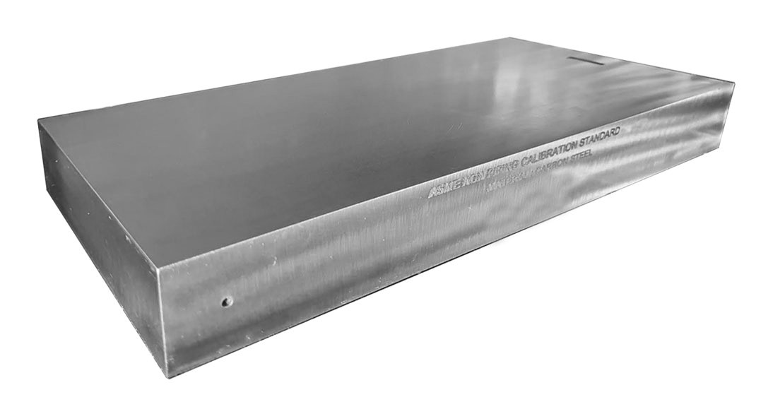
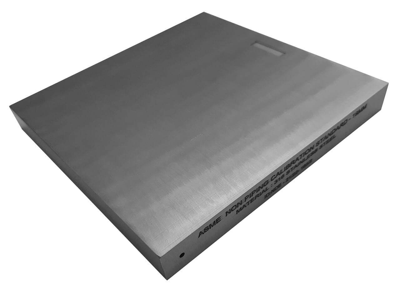
ASME Sec V Basic Calibration Block (12mm WITH NOTCH) METRIC VERSION This block can be used as a calibration block with a compression probe; however, its main use is as a reference block with either compression or shear wave probes. Its most common uses are for setting test sensitivity prior to inspection, using various depth of individual Side Drilled Holes (SDH) as reference reflectors. The test sensitivity as set by means of Distance amplitude Curve (DAC)/Time Correction Gain (TCG). The block size and reflector locations shall be adequate to perform calibrations for the beam angle(s) and distance range(s) to be used. The block thickness (T) shall be varying according to test object. Acoustic signals from the same reflecting surface will have different amplitudes at different distances from the transducer. Distance amplitude correction (DAC) provides a means of establishing a graphic ‘reference level sensitivity’ as a function of sweep distance on the A-scan display. The use of DAC allows signals reflected from similar discontinuities to be evaluated where signal attenuation as a function of depth has been correlated. Most often DAC will allow for loss in amplitude over material depth (time), graphically on the A-scan display but can also be done electronically by certain instruments. Because near field length and beam spread vary according to transducer size and frequency, and materials vary in attenuation and velocity, a DAC curve must be established for each different situation. DAC may be employed in both longitudinal and shear modes of operation as well as either contact or immersion inspection techniques. A distance amplitude correction curve is constructed from the peak amplitude responses from reflectors of equal area at different distances in the same material. A-scan echoes are displayed at their non-electronically compensated height and the peak amplitude of each signal is marked on the flaw detector screen or, preferably, on a transparent plastic sheet attached to the screen. Reference standards which incorporate side drilled holes (SDH), flat bottom holes (FBH), or notches whereby the reflectors are located at varying depths are commonly used. It is important to recognize that regardless of the type of reflector used, the size and shape of the reflector must be constant. Commercially available reference standards for constructing DAC include ASTM Distance/Area Amplitude and ASTM E1158 Distance Amplitude blocks, NAVSHIPS Test block, and ASME Basic Calibration Blocks Geometry: contains three side-drilled holes at 38mm deep minimum at Ø2.5mm diameter. Hole locations through the thickness are ½T. Also contains two EDM notches measuring 2%T deep x 6mm max wide x 25mm long min. In accordance with ASME Sec V Art. 4 Fig. T-434.2.1. Dimensions: 12mm thick x 152mm wide x 100mm long.
Inch Version
ASME Sec V Basic Calibration Block (½ WITHOUT NOTCH INCH VERSION)
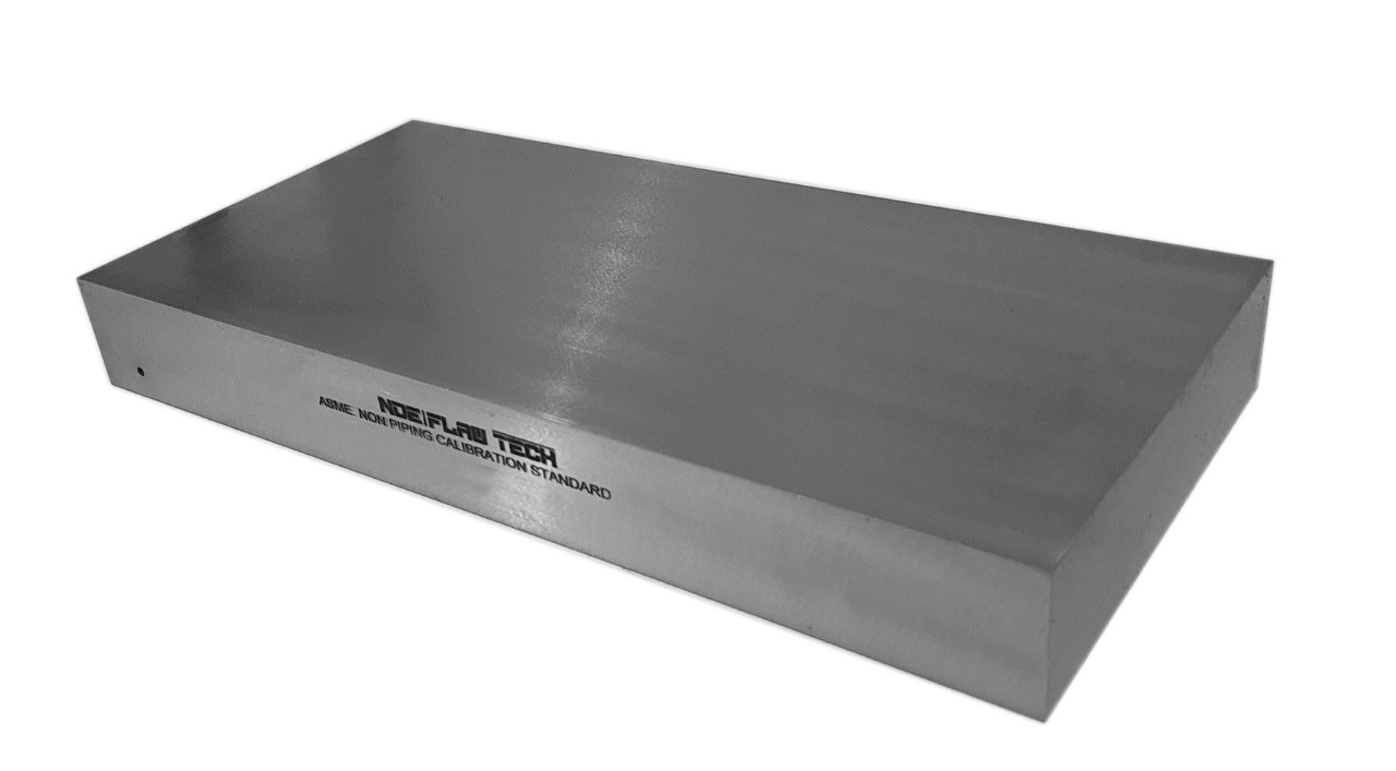
ASME Sec V Basic Calibration Block (½" WITHOUT NOTCH) INCH VERSION This block can be used as a calibration block with a compression probe; however, its main use is as a reference block with either compression or shear wave probes. Its most common uses are for setting test sensitivity prior to inspection, using various depths of individual Side Drilled Holes (SDH) as reference reflectors. The test sensitivity as set by means of Distance amplitude Curve (DAC)/Time Correction Gain (TCG). The block size and reflector locations shall be adequate to perform calibrations for the beam angle(s) and distance range(s) to be used. The block thickness (T) shall be varying according to test object. Acoustic signals from the same reflecting surface will have different amplitudes at different distances from the transducer. Distance amplitude correction (DAC) provides a means of establishing a graphic ‘reference level sensitivity’ as a function of sweep distance on the A-scan display. The use of DAC allows signals reflected from similar discontinuities to be evaluated where signal attenuation as a function of depth has been correlated. Most often DAC will allow for loss in amplitude over material depth (time), graphically on the A-scan display but can also be done electronically by certain instruments. Because near field length and beam spread vary according to transducer size and frequency, and materials vary in attenuation and velocity, a DAC curve must be established for each different situation. DAC may be employed in both longitudinal and shear modes of operation as well as either contact or immersion inspection techniques. A distance amplitude correction curve is constructed from the peak amplitude responses from reflectors of equal area at different distances in the same material. A-scan echoes are displayed at their non-electronically compensated height and the peak amplitude of each signal is marked on the flaw detector screen or, preferably, on a transparent plastic sheet attached to the screen. Reference standards which incorporate side drilled holes (SDH), flat bottom holes (FBH), or notches whereby the reflectors are located at varying depths are commonly used. It is important to recognize that regardless of the type of reflector used, the size and shape of the reflector must be constant. Commercially available reference standards for constructing DAC include ASTM Distance/Area Amplitude and ASTM E1158 Distance Amplitude blocks, NAVSHIPS Test block, and ASME Basic Calibration Blocks Geometry: contains three side-drilled holes at 1.5" deep minimum at 3/32" diameter. Hole locations through the thickness are ½T. In accordance with ASME Sec V Art. 4 Fig. T-434.2.1. Dimensions: ½" thick x 3¼" wide x 3¼" long.
Metric Version
ASME Sec V Basic Calibration Block (12mm WITHOUT NOTCH) METRIC VERSION
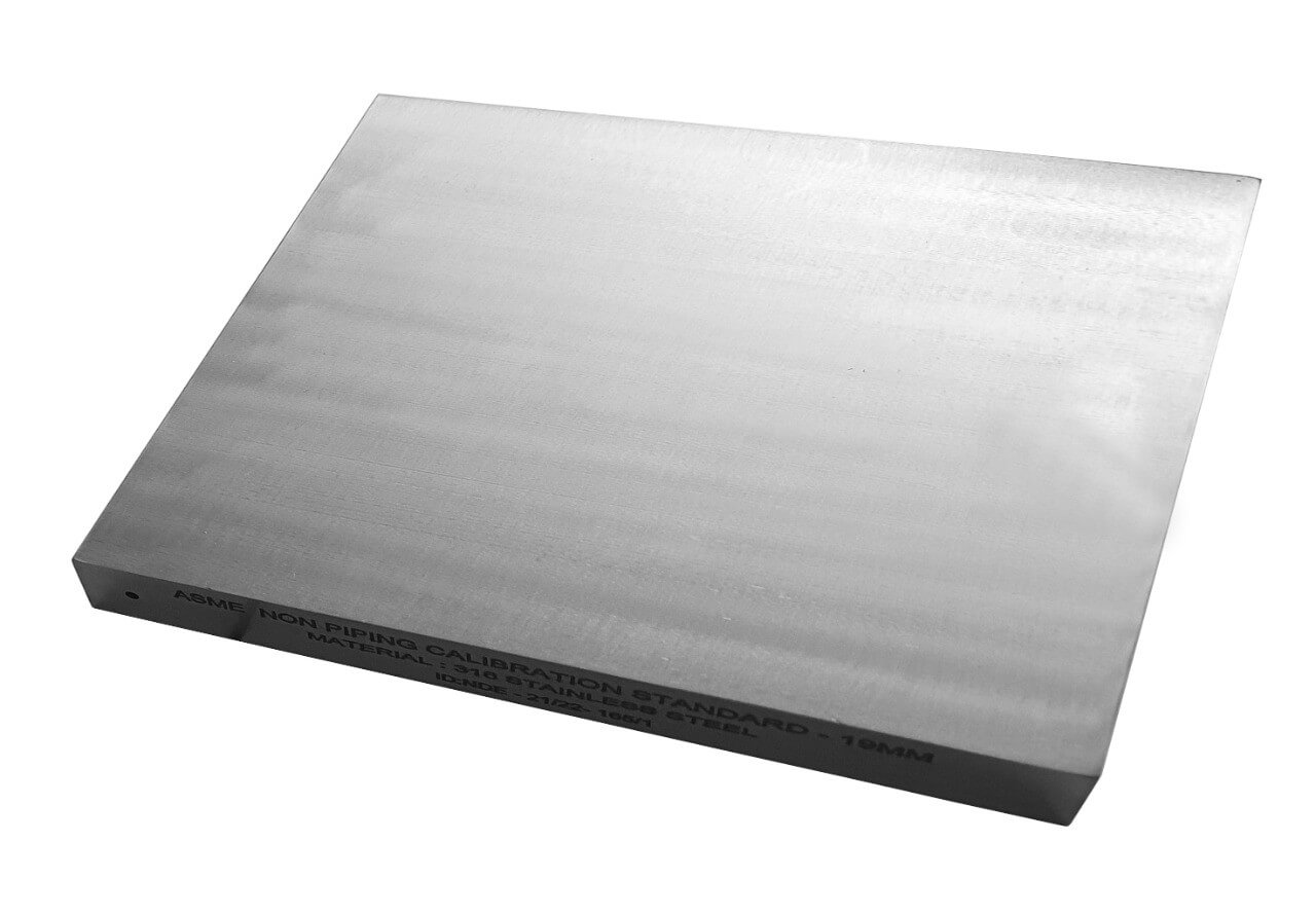
ASME Sec V Basic Calibration Block (12mm WITHOUT NOTCH) METRIC VERSION This block can be used as a calibration block with a compression probe; however, its main use is as a reference block with either compression or shear wave probes. Its most common uses are for setting test sensitivity prior to inspection, using various depth of individual Side Drilled Holes (SDH) as reference reflectors. The test sensitivity as set by means of Distance amplitude Curve (DAC)/Time Correction Gain (TCG). The block size and reflector locations shall be adequate to perform calibrations for the beam angle(s) and distance range(s) to be used. The block thickness (T) shall be varying according to test object. Acoustic signals from the same reflecting surface will have different amplitudes at different distances from the transducer. Distance amplitude correction (DAC) provides a means of establishing a graphic ‘reference level sensitivity’ as a function of sweep distance on the A-scan display. The use of DAC allows signals reflected from similar discontinuities to be evaluated where signal attenuation as a function of depth has been correlated. Most often DAC will allow for loss in amplitude over material depth (time), graphically on the A-scan display but can also be done electronically by certain instruments. Because near field length and beam spread vary according to transducer size and frequency, and materials vary in attenuation and velocity, a DAC curve must be established for each different situation. DAC may be employed in both longitudinal and shear modes of operation as well as either contact or immersion inspection techniques. A distance amplitude correction curve is constructed from the peak amplitude responses from reflectors of equal area at different distances in the same material. A-scan echoes are displayed at their non-electronically compensated height and the peak amplitude of each signal is marked on the flaw detector screen or, preferably, on a transparent plastic sheet attached to the screen. Reference standards which incorporate side drilled holes (SDH), flat bottom holes (FBH), or notches whereby the reflectors are located at varying depths are commonly used. It is important to recognize that regardless of the type of reflector used, the size and shape of the reflector must be constant. Commercially available reference standards for constructing DAC include ASTM Distance/Area Amplitude and ASTM E1158 Distance Amplitude blocks, NAVSHIPS Test block, and ASME Basic Calibration Blocks Geometry: contains three side-drilled holes at 38mm deep minimum at Ø2.5mm diameter. Hole locations through the thickness are ½T. In accordance with ASME Sec V Art. 4 Fig. T-434.2.1. Dimensions: 12mm thick x 80mm wide x 80mm long.
Metric Version
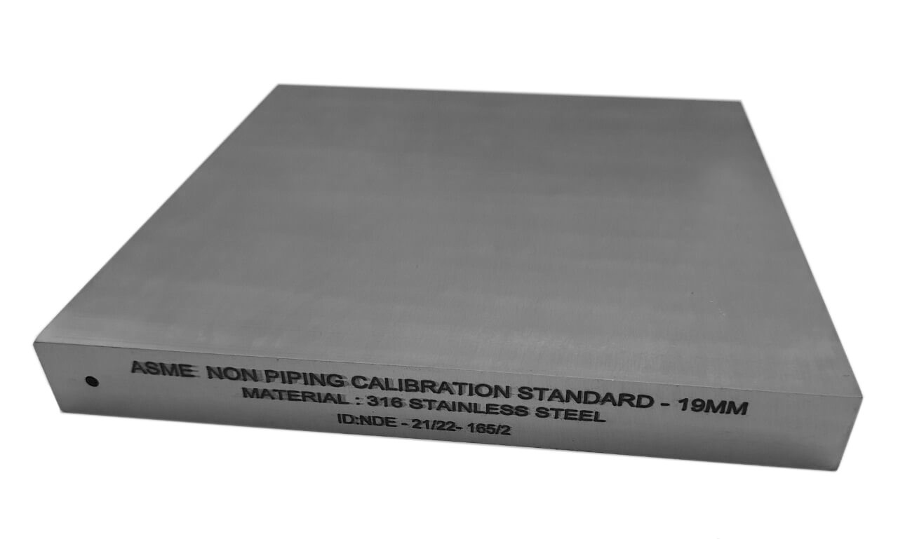
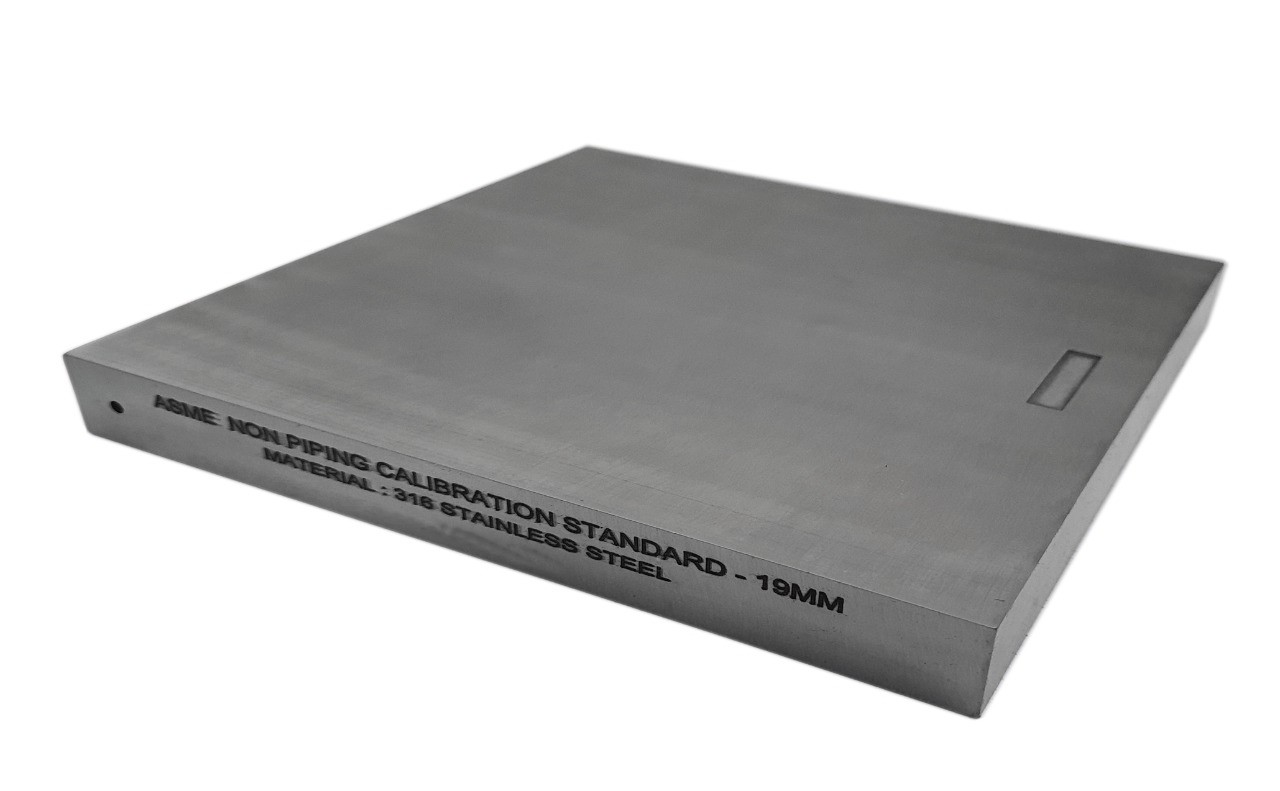
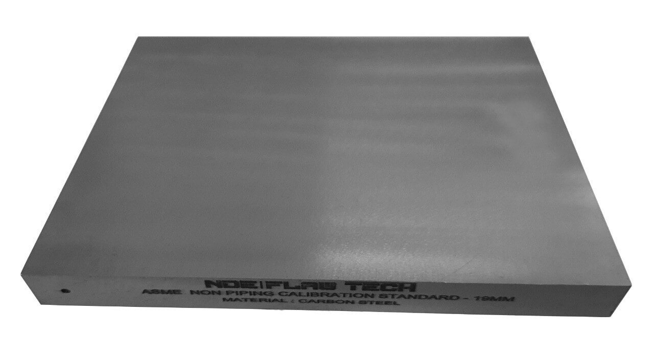
ASME Sec V Basic Calibration Block (19mm HALF SKIP WITH NOTCH) METRIC VERSION
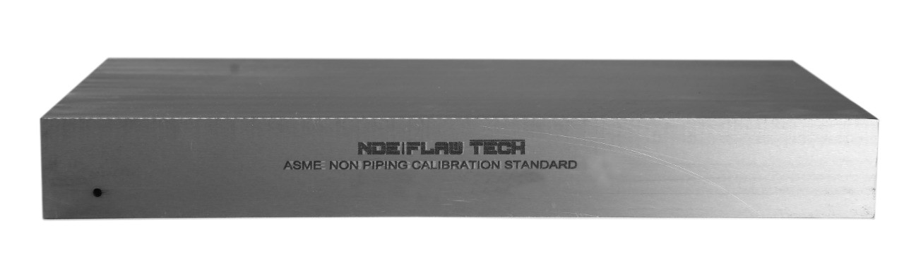
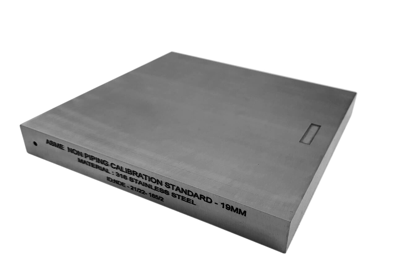
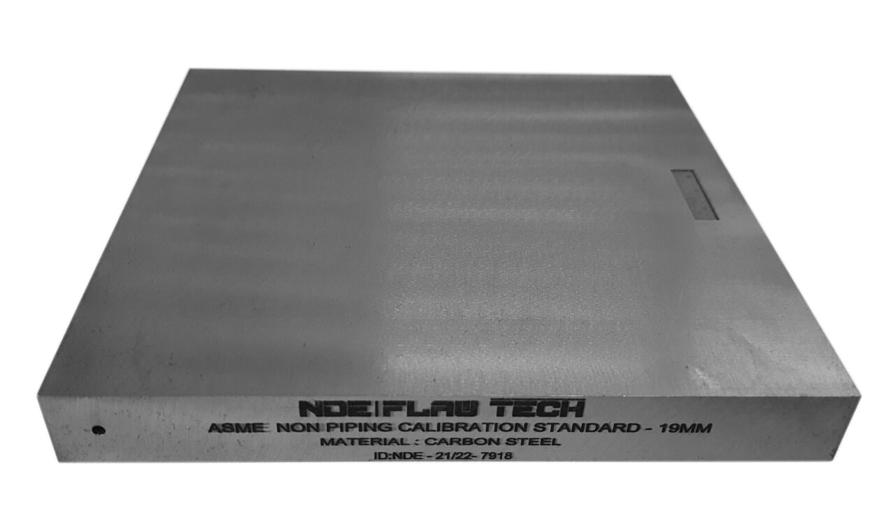
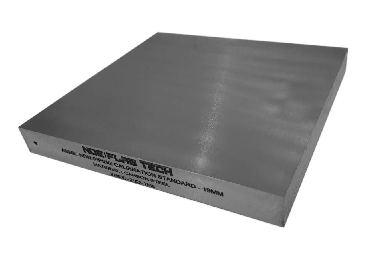
ASME Sec V Basic Calibration Block (19mm HALF SKIP WITH NOTCH) METRIC VERSION This block can be used as a calibration block with a compression probe; however, its main use is as a reference block with either compression or shear wave probes. Its most common uses are for setting test sensitivity prior to inspection, using various depth of individual Side Drilled Holes (SDH) as reference reflectors. The test sensitivity as set by means of Distance amplitude Curve (DAC)/Time Correction Gain (TCG). The block size and reflector locations shall be adequate to perform calibrations for the beam angle(s) and distance range(s) to be used. The block thickness (T) shall be varying according to test object. Acoustic signals from the same reflecting surface will have different amplitudes at different distances from the transducer. Distance amplitude correction (DAC) provides a means of establishing a graphic ‘reference level sensitivity’ as a function of sweep distance on the A-scan display. The use of DAC allows signals reflected from similar discontinuities to be evaluated where signal attenuation as a function of depth has been correlated. Most often DAC will allow for loss in amplitude over material depth (time), graphically on the A-scan display but can also be done electronically by certain instruments. Because near field length and beam spread vary according to transducer size and frequency, and materials vary in attenuation and velocity, a DAC curve must be established for each different situation. DAC may be employed in both longitudinal and shear modes of operation as well as either contact or immersion inspection techniques. A distance amplitude correction curve is constructed from the peak amplitude responses from reflectors of equal area at different distances in the same material. A-scan echoes are displayed at their non-electronically compensated height and the peak amplitude of each signal is marked on the flaw detector screen or, preferably, on a transparent plastic sheet attached to the screen. Reference standards which incorporate side drilled holes (SDH), flat bottom holes (FBH), or notches whereby the reflectors are located at varying depths are commonly used. It is important to recognize that regardless of the type of reflector used, the size and shape of the reflector must be constant. Commercially available reference standards for constructing DAC include ASTM Distance/Area Amplitude and ASTM E1158 Distance Amplitude blocks, NAVSHIPS Test block, and ASME Basic Calibration Blocks Geometry: contains three side-drilled holes at 38mm deep minimum at Ø2.5mm diameter. Hole locations through the thickness are ¼, ½ and ¾T. Also contains two EDM notches measuring 2%T deep x 6mm max wide x 25mm long min. In accordance with ASME Sec V Art. 4 Fig. T-434.2.1. Dimensions: 19mm thick x 152mm wide x 120mm long.
Inch Version
ASME Sec V Basic Calibration Block (¾" HALF SKIP WITH NOTCH) INCH VERSION
ASME Sec V Basic Calibration Block (¾" HALF SKIP WITH NOTCH) INCH VERSION This block can be used as a calibration block with a compression probe; however, its main use is as a reference block with either compression or shear wave probes. Its most common uses are for setting test sensitivity prior to inspection, using various depth of individual Side Drilled Holes (SDH) as reference reflectors. The test sensitivity as set by means of Distance amplitude Curve (DAC)/Time Correction Gain (TCG). The block size and reflector locations shall be adequate to perform calibrations for the beam angle(s) and distance range(s) to be used. The block thickness (T) shall be varying according to test object. Acoustic signals from the same reflecting surface will have different amplitudes at different distances from the transducer. Distance amplitude correction (DAC) provides a means of establishing a graphic ‘reference level sensitivity’ as a function of sweep distance on the A-scan display. The use of DAC allows signals reflected from similar discontinuities to be evaluated where signal attenuation as a function of depth has been correlated. Most often DAC will allow for loss in amplitude over material depth (time), graphically on the A-scan display but can also be done electronically by certain instruments. Because near field length and beam spread vary according to transducer size and frequency, and materials vary in attenuation and velocity, a DAC curve must be established for each different situation. DAC may be employed in both longitudinal and shear modes of operation as well as either contact or immersion inspection techniques. A distance amplitude correction curve is constructed from the peak amplitude responses from reflectors of equal area at different distances in the same material. A-scan echoes are displayed at their non-electronically compensated height and the peak amplitude of each signal is marked on the flaw detector screen or, preferably, on a transparent plastic sheet attached to the screen. Reference standards which incorporate side drilled holes (SDH), flat bottom holes (FBH), or notches whereby the reflectors are located at varying depths are commonly used. It is important to recognize that regardless of the type of reflector used, the size and shape of the reflector must be constant. Commercially available reference standards for constructing DAC include ASTM Distance/Area Amplitude and ASTM E1158 Distance Amplitude blocks, NAVSHIPS Test block, and ASME Basic Calibration Blocks Geometry: contains three side-drilled holes at 1.5" deep minimum at 3/32" diameter. Hole locations through the thickness are ¼, ½ and ¾T. Also contains two EDM notches measuring 2%T deep x 1/4" max wide x 1.0" long min. In accordance with ASME Sec V Art. 4 Fig. T-434.2.1. Dimensions: ¾" thick x 6" wide x 4¾" long.
Inch Version
ASME Sec V Basic Calibration Block (¾
ASME Sec V Basic Calibration Block (¾" HALF SKIP WITHOUT NOTCH) INCH VERSION This block can be used as a calibration block with a compression probe; however, its main use is as a reference block with either compression or shear wave probes. Its most common uses are for setting test sensitivity prior to inspection, using various depths of individual Side Drilled Holes (SDH) as reference reflectors. The test sensitivity is set by means of Distance amplitude Curve (DAC)/Time Correction Gain (TCG). The block size and reflector locations shall be adequate to perform calibrations for the beam angle(s) and distance range(s) to be used. The block thickness (T) shall vary according to the test object. Acoustic signals from the same reflecting surface will have different amplitudes at different distances from the transducer. Distance amplitude correction (DAC) provides a means of establishing a graphic ‘reference level sensitivity’ as a function of sweep distance on the A-scan display. The use of DAC allows signals reflected from similar discontinuities to be evaluated where signal attenuation as a function of depth has been correlated. Most often DAC will allow for loss in amplitude over material depth (time), graphically on the A-scan display but can also be done electronically by certain instruments. Because the near-field length and beam spread vary according to transducer size and frequency, and materials vary in attenuation and velocity, a DAC curve must be established for each different situation. DAC may be employed in both longitudinal and shear modes of operation as well as either contact or immersion inspection techniques. A distance amplitude correction curve is constructed from the peak amplitude responses from reflectors of equal area at different distances in the same material. A-scan echoes are displayed at their non-electronically compensated height and the peak amplitude of each signal is marked on the flaw detector screen or, preferably, on a transparent plastic sheet attached to the screen. Reference standards that incorporate side drilled holes (SDH), flat bottom holes (FBH), or notches whereby the reflectors are located at varying depths are commonly used. It is important to recognize that regardless of the type of reflector used, the size and shape of the reflector must be constant. Commercially available reference standards for constructing DAC include ASTM Distance/Area Amplitude and ASTM E1158 Distance Amplitude blocks, NAVSHIPS Test block, and ASME Basic Calibration Blocks Geometry: contains three side-drilled holes at 1.5" deep minimum at 3/32" diameter. Hole locations through the thickness are ¼, ½, and ¾T. In accordance with ASME Sec V Art. 4 Fig. T-434.2.1. Dimensions: ¾" thick x 3¼" wide x 3¼" long.
Metric Version
ASME Sec V Basic Calibration Block (19mm HALF SKIP WITHOUT NOTCH) METRIC VERSION
ASME Sec V Basic Calibration Block (19mm HALF SKIP WITHOUT NOTCH) METRIC VERSION This block can be used as a calibration block with a compression probe; however, its main use is as a reference block with either compression or shear wave probes. Its most common uses are for setting test sensitivity prior to inspection, using various depth of individual Side Drilled Holes (SDH) as reference reflectors. The test sensitivity as set by means of Distance amplitude Curve (DAC)/Time Correction Gain (TCG). The block size and reflector locations shall be adequate to perform calibrations for the beam angle(s) and distance range(s) to be used. The block thickness (T) shall be varying according to test object. Acoustic signals from the same reflecting surface will have different amplitudes at different distances from the transducer. Distance amplitude correction (DAC) provides a means of establishing a graphic ‘reference level sensitivity’ as a function of sweep distance on the A-scan display. The use of DAC allows signals reflected from similar discontinuities to be evaluated where signal attenuation as a function of depth has been correlated. Most often DAC will allow for loss in amplitude over material depth (time), graphically on the A-scan display but can also be done electronically by certain instruments. Because near field length and beam spread vary according to transducer size and frequency, and materials vary in attenuation and velocity, a DAC curve must be established for each different situation. DAC may be employed in both longitudinal and shear modes of operation as well as either contact or immersion inspection techniques. A distance amplitude correction curve is constructed from the peak amplitude responses from reflectors of equal area at different distances in the same material. A-scan echoes are displayed at their non-electronically compensated height and the peak amplitude of each signal is marked on the flaw detector screen or, preferably, on a transparent plastic sheet attached to the screen. Reference standards which incorporate side drilled holes (SDH), flat bottom holes (FBH), or notches whereby the reflectors are located at varying depths are commonly used. It is important to recognize that regardless of the type of reflector used, the size and shape of the reflector must be constant. Commercially available reference standards for constructing DAC include ASTM Distance/Area Amplitude and ASTM E1158 Distance Amplitude blocks, NAVSHIPS Test block, and ASME Basic Calibration Blocks Geometry: contains three side-drilled holes at 38mm deep minimum at Ø2.5mm diameter. Hole locations through the thickness are ¼, ½ and ¾T. In accordance with ASME Sec V Art. 4 Fig. T-434.2.1. Dimensions: 19mm thick x 80mm wide x 75mm long.
Inch Version
ASME Sec V Basic Calibration Block (¾" FULL SKIP WITH NOTCH) INCH VERSION
ASME Sec V Basic Calibration Block (¾" FULL SKIP WITH NOTCH) INCH VERSION This block can be used as a calibration block with a compression probe; however, its main use is as a reference block with either compression or shear wave probes. Its most common uses are for setting test sensitivity prior to inspection, using various depth of individual Side Drilled Holes (SDH) as reference reflectors. The test sensitivity as set by means of Distance amplitude Curve (DAC)/Time Correction Gain (TCG). The block size and reflector locations shall be adequate to perform calibrations for the beam angle(s) and distance range(s) to be used. The block thickness (T) shall be varying according to test object. Acoustic signals from the same reflecting surface will have different amplitudes at different distances from the transducer. Distance amplitude correction (DAC) provides a means of establishing a graphic ‘reference level sensitivity’ as a function of sweep distance on the A-scan display. The use of DAC allows signals reflected from similar discontinuities to be evaluated where signal attenuation as a function of depth has been correlated. Most often DAC will allow for loss in amplitude over material depth (time), graphically on the A-scan display but can also be done electronically by certain instruments. Because near field length and beam spread vary according to transducer size and frequency, and materials vary in attenuation and velocity, a DAC curve must be established for each different situation. DAC may be employed in both longitudinal and shear modes of operation as well as either contact or immersion inspection techniques. A distance amplitude correction curve is constructed from the peak amplitude responses from reflectors of equal area at different distances in the same material. A-scan echoes are displayed at their non-electronically compensated height and the peak amplitude of each signal is marked on the flaw detector screen or, preferably, on a transparent plastic sheet attached to the screen. Reference standards which incorporate side drilled holes (SDH), flat bottom holes (FBH), or notches whereby the reflectors are located at varying depths are commonly used. It is important to recognize that regardless of the type of reflector used, the size and shape of the reflector must be constant. Commercially available reference standards for constructing DAC include ASTM Distance/Area Amplitude and ASTM E1158 Distance Amplitude blocks, NAVSHIPS Test block, and ASME Basic Calibration Blocks Geometry: contains three side-drilled holes at 1.5" deep minimum at 3/32" diameter. Hole locations through the thickness are ¼, ½ and ¾T. Also contains two EDM notches measuring 2%T deep x 1/4" max wide x 1.0" long min. In accordance with ASME Sec V Art. 4 Fig. T-434.2.1. Dimensions: ¾" thick x 6" wide x 5¼" long.
Metric Version
ASME Sec V Basic Calibration Block (19mm FULL SKIP WITH NOTCH) METRIC VERSION
ASME Sec V Basic Calibration Block (19mm FULL SKIP WITH NOTCH) METRIC VERSION This block can be used as a calibration block with a compression probe; however, its main use is as a reference block with either compression or shear wave probes. Its most common uses are for setting test sensitivity prior to inspection, using various depth of individual Side Drilled Holes (SDH) as reference reflectors. The test sensitivity as set by means of Distance amplitude Curve (DAC)/Time Correction Gain (TCG). The block size and reflector locations shall be adequate to perform calibrations for the beam angle(s) and distance range(s) to be used. The block thickness (T) shall be varying according to test object. Acoustic signals from the same reflecting surface will have different amplitudes at different distances from the transducer. Distance amplitude correction (DAC) provides a means of establishing a graphic ‘reference level sensitivity’ as a function of sweep distance on the A-scan display. The use of DAC allows signals reflected from similar discontinuities to be evaluated where signal attenuation as a function of depth has been correlated. Most often DAC will allow for loss in amplitude over material depth (time), graphically on the A-scan display but can also be done electronically by certain instruments. Because near field length and beam spread vary according to transducer size and frequency, and materials vary in attenuation and velocity, a DAC curve must be established for each different situation. DAC may be employed in both longitudinal and shear modes of operation as well as either contact or immersion inspection techniques. A distance amplitude correction curve is constructed from the peak amplitude responses from reflectors of equal area at different distances in the same material. A-scan echoes are displayed at their non-electronically compensated height and the peak amplitude of each signal is marked on the flaw detector screen or, preferably, on a transparent plastic sheet attached to the screen. Reference standards which incorporate side drilled holes (SDH), flat bottom holes (FBH), or notches whereby the reflectors are located at varying depths are commonly used. It is important to recognize that regardless of the type of reflector used, the size and shape of the reflector must be constant. Commercially available reference standards for constructing DAC include ASTM Distance/Area Amplitude and ASTM E1158 Distance Amplitude blocks, NAVSHIPS Test block, and ASME Basic Calibration Blocks Geometry: contains three side-drilled holes at 38mm deep minimum at Ø2.5mm diameter. Hole locations through the thickness are ¼, ½ and ¾T. Also contains two EDM notches measuring 2%T deep x 6mm max wide x 25mm long min. In accordance with ASME Sec V Art. 4 Fig. T-434.2.1. Dimensions: 19mm thick x 152mm wide x 140mm long.
Inch Version
ASME Sec V Basic Calibration Block (¾" FULL SKIP WITHOUT NOTCH) INCH VERSION
ASME Sec V Basic Calibration Block (¾" FULL SKIP WITHOUT NOTCH) INCH VERSION This block can be used as a calibration block with a compression probe; however, its main use is as a reference block with either compression or shear wave probes. Its most common uses are for setting test sensitivity prior to inspection, using various depth of individual Side Drilled Holes (SDH) as reference reflectors. The test sensitivity as set by means of Distance amplitude Curve (DAC)/Time Correction Gain (TCG). The block size and reflector locations shall be adequate to perform calibrations for the beam angle(s) and distance range(s) to be used. The block thickness (T) shall be varying according to test object. Acoustic signals from the same reflecting surface will have different amplitudes at different distances from the transducer. Distance amplitude correction (DAC) provides a means of establishing a graphic ‘reference level sensitivity’ as a function of sweep distance on the A-scan display. The use of DAC allows signals reflected from similar discontinuities to be evaluated where signal attenuation as a function of depth has been correlated. Most often DAC will allow for loss in amplitude over material depth (time), graphically on the A-scan display but can also be done electronically by certain instruments. Because near field length and beam spread vary according to transducer size and frequency, and materials vary in attenuation and velocity, a DAC curve must be established for each different situation. DAC may be employed in both longitudinal and shear modes of operation as well as either contact or immersion inspection techniques. A distance amplitude correction curve is constructed from the peak amplitude responses from reflectors of equal area at different distances in the same material. A-scan echoes are displayed at their non-electronically compensated height and the peak amplitude of each signal is marked on the flaw detector screen or, preferably, on a transparent plastic sheet attached to the screen. Reference standards which incorporate side drilled holes (SDH), flat bottom holes (FBH), or notches whereby the reflectors are located at varying depths are commonly used. It is important to recognize that regardless of the type of reflector used, the size and shape of the reflector must be constant. Commercially available reference standards for constructing DAC include ASTM Distance/Area Amplitude and ASTM E1158 Distance Amplitude blocks, NAVSHIPS Test block, and ASME Basic Calibration Blocks Geometry: contains three side-drilled holes at 1.5" deep minimum at 3/32" diameter. Hole locations through the thickness are ¼, ½ and ¾T. In accordance with ASME Sec V Art. 4 Fig. T-434.2.1. Dimensions: ¾" thick x 3¼" wide x 4¾" long.
Metric Version
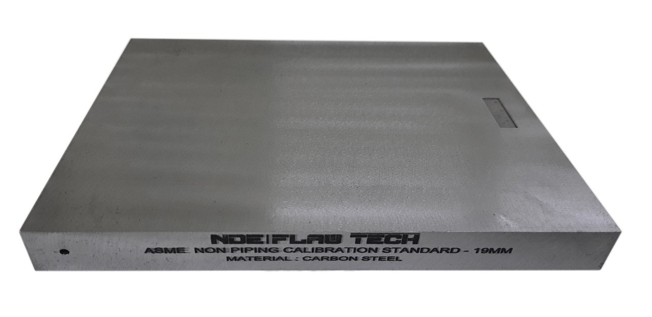
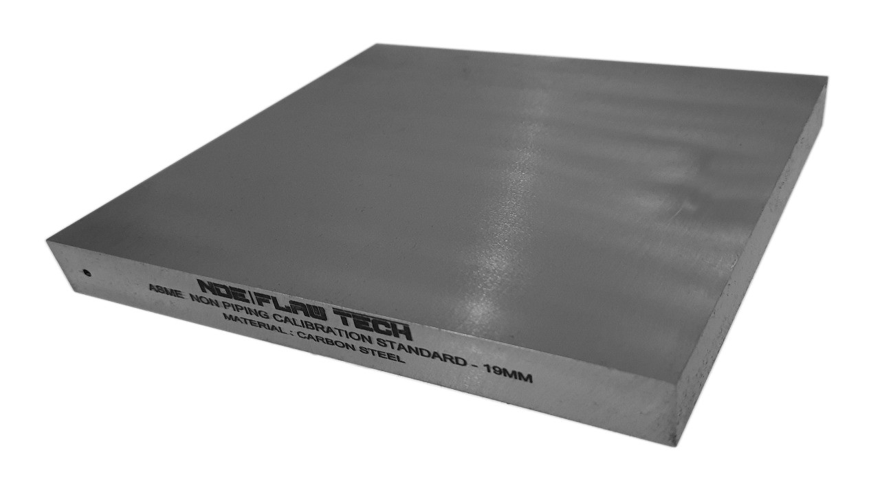
ASME Sec V Basic Calibration Block (19mm FULL SKIP WITHOUT NOTCH) METRIC VERSION
ASME Sec V Basic Calibration Block (19mm FULL SKIP WITHOUT NOTCH) METRIC VERSION This block can be used as a calibration block with a compression probe; however, its main use is as a reference block with either compression or shear wave probes. Its most common uses are for setting test sensitivity prior to inspection, using various depth of individual Side Drilled Holes (SDH) as reference reflectors. The test sensitivity as set by means of Distance amplitude Curve (DAC)/Time Correction Gain (TCG). The block size and reflector locations shall be adequate to perform calibrations for the beam angle(s) and distance range(s) to be used. The block thickness (T) shall be varying according to test object. Acoustic signals from the same reflecting surface will have different amplitudes at different distances from the transducer. Distance amplitude correction (DAC) provides a means of establishing a graphic ‘reference level sensitivity’ as a function of sweep distance on the A-scan display. The use of DAC allows signals reflected from similar discontinuities to be evaluated where signal attenuation as a function of depth has been correlated. Most often DAC will allow for loss in amplitude over material depth (time), graphically on the A-scan display but can also be done electronically by certain instruments. Because near field length and beam spread vary according to transducer size and frequency, and materials vary in attenuation and velocity, a DAC curve must be established for each different situation. DAC may be employed in both longitudinal and shear modes of operation as well as either contact or immersion inspection techniques. A distance amplitude correction curve is constructed from the peak amplitude responses from reflectors of equal area at different distances in the same material. A-scan echoes are displayed at their non-electronically compensated height and the peak amplitude of each signal is marked on the flaw detector screen or, preferably, on a transparent plastic sheet attached to the screen. Reference standards which incorporate side drilled holes (SDH), flat bottom holes (FBH), or notches whereby the reflectors are located at varying depths are commonly used. It is important to recognize that regardless of the type of reflector used, the size and shape of the reflector must be constant. Commercially available reference standards for constructing DAC include ASTM Distance/Area Amplitude and ASTM E1158 Distance Amplitude blocks, NAVSHIPS Test block, and ASME Basic Calibration Blocks Geometry: contains three side-drilled holes at 38mm deep minimum at Ø2.5mm diameter. Hole locations through the thickness are ¼, ½ and ¾T. In accordance with ASME Sec V Art. 4 Fig. T-434.2.1. Dimensions: 19mm thick x 80mm wide x 120mm long.
Inch Version
ASME Sec V Basic Calibration Block (¾" - 1½ SKIP WITH NOTCH) INCH VERSION
ASME Sec V Basic Calibration Block (¾" - 1½ SKIP WITH NOTCH) INCH VERSION This block can be used as a calibration block with a compression probe; however, its main use is as a reference block with either compression or shear wave probes. Its most common uses are for setting test sensitivity prior to inspection, using various depth of individual Side Drilled Holes (SDH) as reference reflectors. The test sensitivity as set by means of Distance amplitude Curve (DAC)/Time Correction Gain (TCG). The block size and reflector locations shall be adequate to perform calibrations for the beam angle(s) and distance range(s) to be used. The block thickness (T) shall be varying according to test object. Acoustic signals from the same reflecting surface will have different amplitudes at different distances from the transducer. Distance amplitude correction (DAC) provides a means of establishing a graphic ‘reference level sensitivity’ as a function of sweep distance on the A-scan display. The use of DAC allows signals reflected from similar discontinuities to be evaluated where signal attenuation as a function of depth has been correlated. Most often DAC will allow for loss in amplitude over material depth (time), graphically on the A-scan display but can also be done electronically by certain instruments. Because near field length and beam spread vary according to transducer size and frequency, and materials vary in attenuation and velocity, a DAC curve must be established for each different situation. DAC may be employed in both longitudinal and shear modes of operation as well as either contact or immersion inspection techniques. A distance amplitude correction curve is constructed from the peak amplitude responses from reflectors of equal area at different distances in the same material. A-scan echoes are displayed at their non-electronically compensated height and the peak amplitude of each signal is marked on the flaw detector screen or, preferably, on a transparent plastic sheet attached to the screen. Reference standards which incorporate side drilled holes (SDH), flat bottom holes (FBH), or notches whereby the reflectors are located at varying depths are commonly used. It is important to recognize that regardless of the type of reflector used, the size and shape of the reflector must be constant. Commercially available reference standards for constructing DAC include ASTM Distance/Area Amplitude and ASTM E1158 Distance Amplitude blocks, NAVSHIPS Test block, and ASME Basic Calibration Blocks Geometry: contains three side-drilled holes at 1.5" deep minimum at 3/32" diameter. Hole locations through the thickness are ¼, ½ and ¾T. Also contains two EDM notches measuring 2%T deep x 1/4" max wide x 1.0" long min. In accordance with ASME Sec V Art. 4 Fig. T-434.2.1. Dimensions: ¾" thick x 6" wide x 6¼" long.
Metric Version
ASME Sec V Basic Calibration Block (19mm - 1½ SKIP WITH NOTCH) METRIC VERSION
ASME Sec V Basic Calibration Block (19mm - 1½ SKIP WITH NOTCH) METRIC VERSION This block can be used as a calibration block with a compression probe; however, its main use is as a reference block with either compression or shear wave probes. Its most common uses are for setting test sensitivity prior to inspection, using various depth of individual Side Drilled Holes (SDH) as reference reflectors. The test sensitivity as set by means of Distance amplitude Curve (DAC)/Time Correction Gain (TCG). The block size and reflector locations shall be adequate to perform calibrations for the beam angle(s) and distance range(s) to be used. The block thickness (T) shall be varying according to test object. Acoustic signals from the same reflecting surface will have different amplitudes at different distances from the transducer. Distance amplitude correction (DAC) provides a means of establishing a graphic ‘reference level sensitivity’ as a function of sweep distance on the A-scan display. The use of DAC allows signals reflected from similar discontinuities to be evaluated where signal attenuation as a function of depth has been correlated. Most often DAC will allow for loss in amplitude over material depth (time), graphically on the A-scan display but can also be done electronically by certain instruments. Because near field length and beam spread vary according to transducer size and frequency, and materials vary in attenuation and velocity, a DAC curve must be established for each different situation. DAC may be employed in both longitudinal and shear modes of operation as well as either contact or immersion inspection techniques. A distance amplitude correction curve is constructed from the peak amplitude responses from reflectors of equal area at different distances in the same material. A-scan echoes are displayed at their non-electronically compensated height and the peak amplitude of each signal is marked on the flaw detector screen or, preferably, on a transparent plastic sheet attached to the screen. Reference standards which incorporate side drilled holes (SDH), flat bottom holes (FBH), or notches whereby the reflectors are located at varying depths are commonly used. It is important to recognize that regardless of the type of reflector used, the size and shape of the reflector must be constant. Commercially available reference standards for constructing DAC include ASTM Distance/Area Amplitude and ASTM E1158 Distance Amplitude blocks, NAVSHIPS Test block, and ASME Basic Calibration Blocks Geometry: contains three side-drilled holes at 38mm deep minimum at Ø2.5mm diameter. Hole locations through the thickness are ¼, ½ and ¾T. Also contains two EDM notches measuring 2%T deep x 6mm max wide x 25mm long min. In accordance with ASME Sec V Art. 4 Fig. T-434.2.1. Dimensions: 19mm thick x 152mm wide x 160mm long.
Inch Version
ASME Sec V Basic Calibration Block (¾"- 1½ SKIP WITHOUT NOTCH) INCH VERSION
ASME Sec V Basic Calibration Block (¾"- 1½ SKIP WITHOUT NOTCH) INCH VERSION This block can be used as a calibration block with a compression probe; however, its main use is as a reference block with either compression or shear wave probes. Its most common uses are for setting test sensitivity prior to inspection, using various depth of individual Side Drilled Holes (SDH) as reference reflectors. The test sensitivity as set by means of Distance amplitude Curve (DAC)/Time Correction Gain (TCG). The block size and reflector locations shall be adequate to perform calibrations for the beam angle(s) and distance range(s) to be used. The block thickness (T) shall be varying according to test object. Acoustic signals from the same reflecting surface will have different amplitudes at different distances from the transducer. Distance amplitude correction (DAC) provides a means of establishing a graphic ‘reference level sensitivity’ as a function of sweep distance on the A-scan display. The use of DAC allows signals reflected from similar discontinuities to be evaluated where signal attenuation as a function of depth has been correlated. Most often DAC will allow for loss in amplitude over material depth (time), graphically on the A-scan display but can also be done electronically by certain instruments. Because near field length and beam spread vary according to transducer size and frequency, and materials vary in attenuation and velocity, a DAC curve must be established for each different situation. DAC may be employed in both longitudinal and shear modes of operation as well as either contact or immersion inspection techniques. A distance amplitude correction curve is constructed from the peak amplitude responses from reflectors of equal area at different distances in the same material. A-scan echoes are displayed at their non-electronically compensated height and the peak amplitude of each signal is marked on the flaw detector screen or, preferably, on a transparent plastic sheet attached to the screen. Reference standards which incorporate side drilled holes (SDH), flat bottom holes (FBH), or notches whereby the reflectors are located at varying depths are commonly used. It is important to recognize that regardless of the type of reflector used, the size and shape of the reflector must be constant. Commercially available reference standards for constructing DAC include ASTM Distance/Area Amplitude and ASTM E1158 Distance Amplitude blocks, NAVSHIPS Test block, and ASME Basic Calibration Blocks Geometry: contains three side-drilled holes at 1.5" deep minimum at 3/32" diameter. Hole locations through the thickness are ¼, ½ and ¾T. In accordance with ASME Sec V Art. 4 Fig. T-434.2.1. Dimensions: ¾" thick x 3¼" wide x 6¼" long.
Metric Version
ASME Sec V Basic Calibration Block (19mm - 1½ SKIP WITHOUT NOTCH) METRIC VERSION
ASME Sec V Basic Calibration Block (19mm - 1½ SKIP WITHOUT NOTCH) METRIC VERSION This block can be used as a calibration block with a compression probe; however, its main use is as a reference block with either compression or shear wave probes. Its most common uses are for setting test sensitivity prior to inspection, using various depth of individual Side Drilled Holes (SDH) as reference reflectors. The test sensitivity as set by means of Distance amplitude Curve (DAC)/Time Correction Gain (TCG). The block size and reflector locations shall be adequate to perform calibrations for the beam angle(s) and distance range(s) to be used. The block thickness (T) shall be varying according to test object. Acoustic signals from the same reflecting surface will have different amplitudes at different distances from the transducer. Distance amplitude correction (DAC) provides a means of establishing a graphic ‘reference level sensitivity’ as a function of sweep distance on the A-scan display. The use of DAC allows signals reflected from similar discontinuities to be evaluated where signal attenuation as a function of depth has been correlated. Most often DAC will allow for loss in amplitude over material depth (time), graphically on the A-scan display but can also be done electronically by certain instruments. Because near field length and beam spread vary according to transducer size and frequency, and materials vary in attenuation and velocity, a DAC curve must be established for each different situation. DAC may be employed in both longitudinal and shear modes of operation as well as either contact or immersion inspection techniques. A distance amplitude correction curve is constructed from the peak amplitude responses from reflectors of equal area at different distances in the same material. A-scan echoes are displayed at their non-electronically compensated height and the peak amplitude of each signal is marked on the flaw detector screen or, preferably, on a transparent plastic sheet attached to the screen. Reference standards which incorporate side drilled holes (SDH), flat bottom holes (FBH), or notches whereby the reflectors are located at varying depths are commonly used. It is important to recognize that regardless of the type of reflector used, the size and shape of the reflector must be constant. Commercially available reference standards for constructing DAC include ASTM Distance/Area Amplitude and ASTM E1158 Distance Amplitude blocks, NAVSHIPS Test block, and ASME Basic Calibration Blocks Geometry: contains three side-drilled holes at 38mm deep minimum at Ø2.5mm diameter. Hole locations through the thickness are ¼, ½ and ¾T. In accordance with ASME Sec V Art. 4 Fig. T-434.2.1. Dimensions: 19mm thick x 80mm wide x 160mm long.
Inch Version
ASME Sec V Basic Calibration Block (1½" HALF SKIP WITH NOTCH) INCH VERSION
ASME Sec V Basic Calibration Block (1½" HALF SKIP WITH NOTCH) INCH VERSION This block can be used as a calibration block with a compression probe; however, its main use is as a reference block with either compression or shear wave probes. Its most common uses are for setting test sensitivity prior to inspection, using various depth of individual Side Drilled Holes (SDH) as reference reflectors. The test sensitivity as set by means of Distance amplitude Curve (DAC)/Time Correction Gain (TCG). The block size and reflector locations shall be adequate to perform calibrations for the beam angle(s) and distance range(s) to be used. The block thickness (T) shall be varying according to test object. Acoustic signals from the same reflecting surface will have different amplitudes at different distances from the transducer. Distance amplitude correction (DAC) provides a means of establishing a graphic ‘reference level sensitivity’ as a function of sweep distance on the A-scan display. The use of DAC allows signals reflected from similar discontinuities to be evaluated where signal attenuation as a function of depth has been correlated. Most often DAC will allow for loss in amplitude over material depth (time), graphically on the A-scan display but can also be done electronically by certain instruments. Because near field length and beam spread vary according to transducer size and frequency, and materials vary in attenuation and velocity, a DAC curve must be established for each different situation. DAC may be employed in both longitudinal and shear modes of operation as well as either contact or immersion inspection techniques. A distance amplitude correction curve is constructed from the peak amplitude responses from reflectors of equal area at different distances in the same material. A-scan echoes are displayed at their non-electronically compensated height and the peak amplitude of each signal is marked on the flaw detector screen or, preferably, on a transparent plastic sheet attached to the screen. Reference standards which incorporate side drilled holes (SDH), flat bottom holes (FBH), or notches whereby the reflectors are located at varying depths are commonly used. It is important to recognize that regardless of the type of reflector used, the size and shape of the reflector must be constant. Commercially available reference standards for constructing DAC include ASTM Distance/Area Amplitude and ASTM E1158 Distance Amplitude blocks, NAVSHIPS Test block, and ASME Basic Calibration Blocks Geometry: contains three side-drilled holes at 1.5" deep minimum at 1/8" diameter. Hole locations through the thickness are ¼, ½ and ¾T. Also contains two EDM notches measuring 2%T deep x 1/4" max wide x 1.0" long min. In accordance with ASME Sec V Art. 4 Fig. T-434.2.1. Dimensions: 1½" thick x 6" wide x 9½" long.
Metric Version
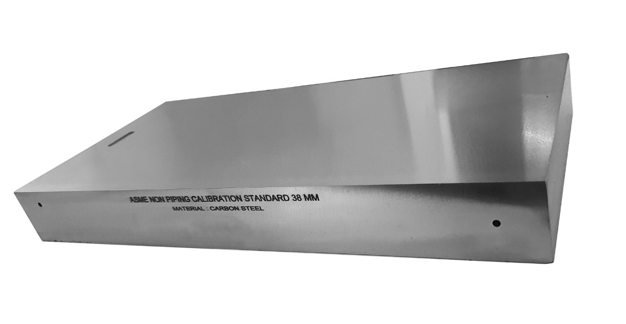
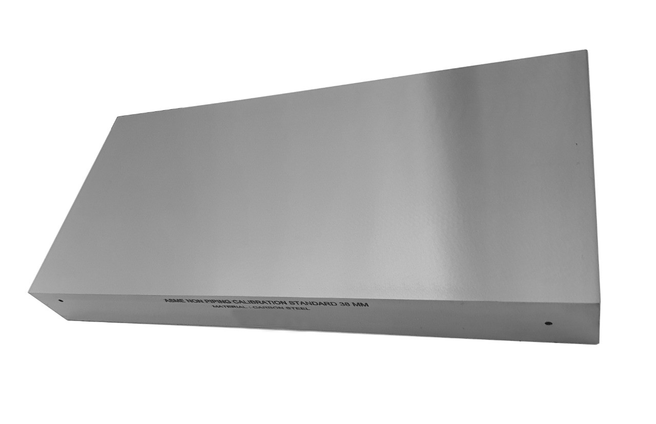
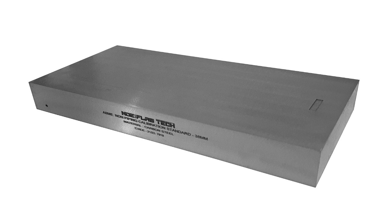
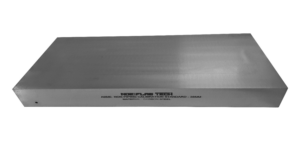
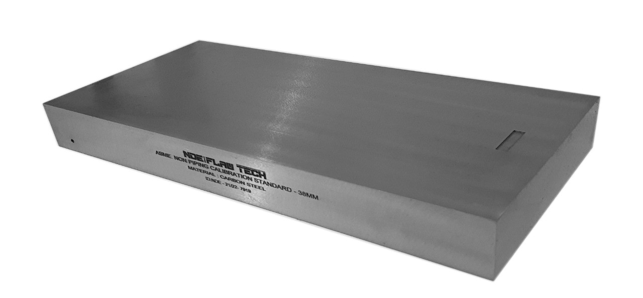
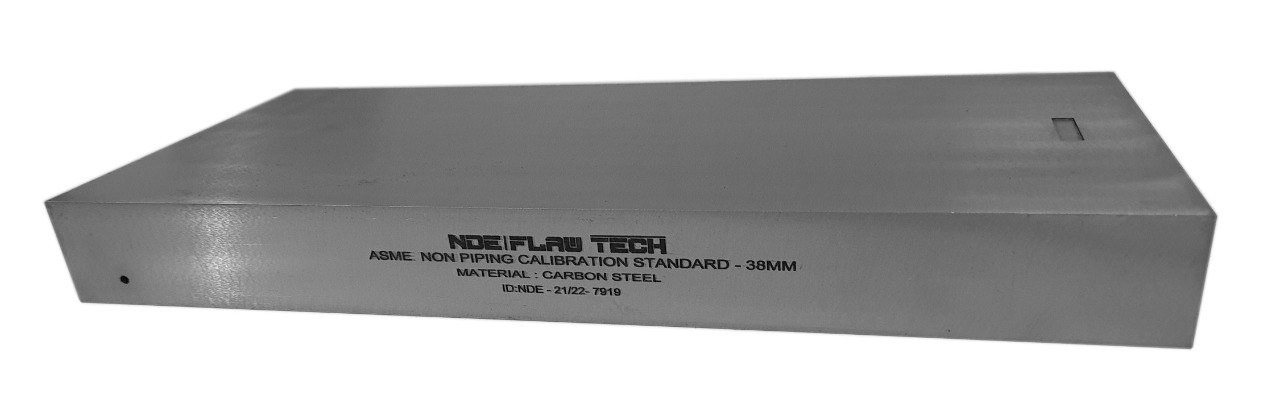
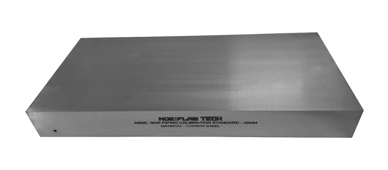
ASME Sec V Basic Calibration Block (38mm HALF SKIP WITH NOTCH) METRIC VERSION
ASME Sec V Basic Calibration Block (38mm HALF SKIP WITH NOTCH) METRIC VERSION This block can be used as a calibration block with a compression probe; however, its main use is as a reference block with either compression or shear wave probes. Its most common uses are for setting test sensitivity prior to inspection, using various depth of individual Side Drilled Holes (SDH) as reference reflectors. The test sensitivity as set by means of Distance amplitude Curve (DAC)/Time Correction Gain (TCG). The block size and reflector locations shall be adequate to perform calibrations for the beam angle(s) and distance range(s) to be used. The block thickness (T) shall be varying according to test object. Acoustic signals from the same reflecting surface will have different amplitudes at different distances from the transducer. Distance amplitude correction (DAC) provides a means of establishing a graphic ‘reference level sensitivity’ as a function of sweep distance on the A-scan display. The use of DAC allows signals reflected from similar discontinuities to be evaluated where signal attenuation as a function of depth has been correlated. Most often DAC will allow for loss in amplitude over material depth (time), graphically on the A-scan display but can also be done electronically by certain instruments. Because near field length and beam spread vary according to transducer size and frequency, and materials vary in attenuation and velocity, a DAC curve must be established for each different situation. DAC may be employed in both longitudinal and shear modes of operation as well as either contact or immersion inspection techniques. A distance amplitude correction curve is constructed from the peak amplitude responses from reflectors of equal area at different distances in the same material. A-scan echoes are displayed at their non-electronically compensated height and the peak amplitude of each signal is marked on the flaw detector screen or, preferably, on a transparent plastic sheet attached to the screen. Reference standards which incorporate side drilled holes (SDH), flat bottom holes (FBH), or notches whereby the reflectors are located at varying depths are commonly used. It is important to recognize that regardless of the type of reflector used, the size and shape of the reflector must be constant. Commercially available reference standards for constructing DAC include ASTM Distance/Area Amplitude and ASTM E1158 Distance Amplitude blocks, NAVSHIPS Test block, and ASME Basic Calibration Blocks Geometry: contains three side-drilled holes at 38mm deep minimum at Ø3mm diameter. Hole locations through the thickness are ¼, ½ and ¾T. Also contains two EDM notches measuring 2%T deep x 6mm max wide x 25mm long min. In accordance with ASME Sec V Art. 4 Fig. T-434.2.1. Dimensions: 38mm thick x 152mm wide x 240mm long.
Inch Version
ASME Sec V Basic Calibration Block (1½" HALF SKIP WITHOUT NOTCH) INCH VERSION
ASME Sec V Basic Calibration Block (1½" HALF SKIP WITHOUT NOTCH) INCH VERSION This block can be used as a calibration block with a compression probe; however, its main use is as a reference block with either compression or shear wave probes. Its most common uses are for setting test sensitivity prior to inspection, using various depth of individual Side Drilled Holes (SDH) as reference reflectors. The test sensitivity as set by means of Distance amplitude Curve (DAC)/Time Correction Gain (TCG). The block size and reflector locations shall be adequate to perform calibrations for the beam angle(s) and distance range(s) to be used. The block thickness (T) shall be varying according to test object. Acoustic signals from the same reflecting surface will have different amplitudes at different distances from the transducer. Distance amplitude correction (DAC) provides a means of establishing a graphic ‘reference level sensitivity’ as a function of sweep distance on the A-scan display. The use of DAC allows signals reflected from similar discontinuities to be evaluated where signal attenuation as a function of depth has been correlated. Most often DAC will allow for loss in amplitude over material depth (time), graphically on the A-scan display but can also be done electronically by certain instruments. Because near field length and beam spread vary according to transducer size and frequency, and materials vary in attenuation and velocity, a DAC curve must be established for each different situation. DAC may be employed in both longitudinal and shear modes of operation as well as either contact or immersion inspection techniques. A distance amplitude correction curve is constructed from the peak amplitude responses from reflectors of equal area at different distances in the same material. A-scan echoes are displayed at their non-electronically compensated height and the peak amplitude of each signal is marked on the flaw detector screen or, preferably, on a transparent plastic sheet attached to the screen. Reference standards which incorporate side drilled holes (SDH), flat bottom holes (FBH), or notches whereby the reflectors are located at varying depths are commonly used. It is important to recognize that regardless of the type of reflector used, the size and shape of the reflector must be constant. Commercially available reference standards for constructing DAC include ASTM Distance/Area Amplitude and ASTM E1158 Distance Amplitude blocks, NAVSHIPS Test block, and ASME Basic Calibration Blocks Geometry: contains three side-drilled holes at 1.5" deep minimum at 1/8" diameter. Hole locations through the thickness are ¼, ½ and ¾T. In accordance with ASME Sec V Art. 4 Fig. T-434.2.1. Dimensions: 1½" thick x 3¼" wide x 4½" long.
Metric Version
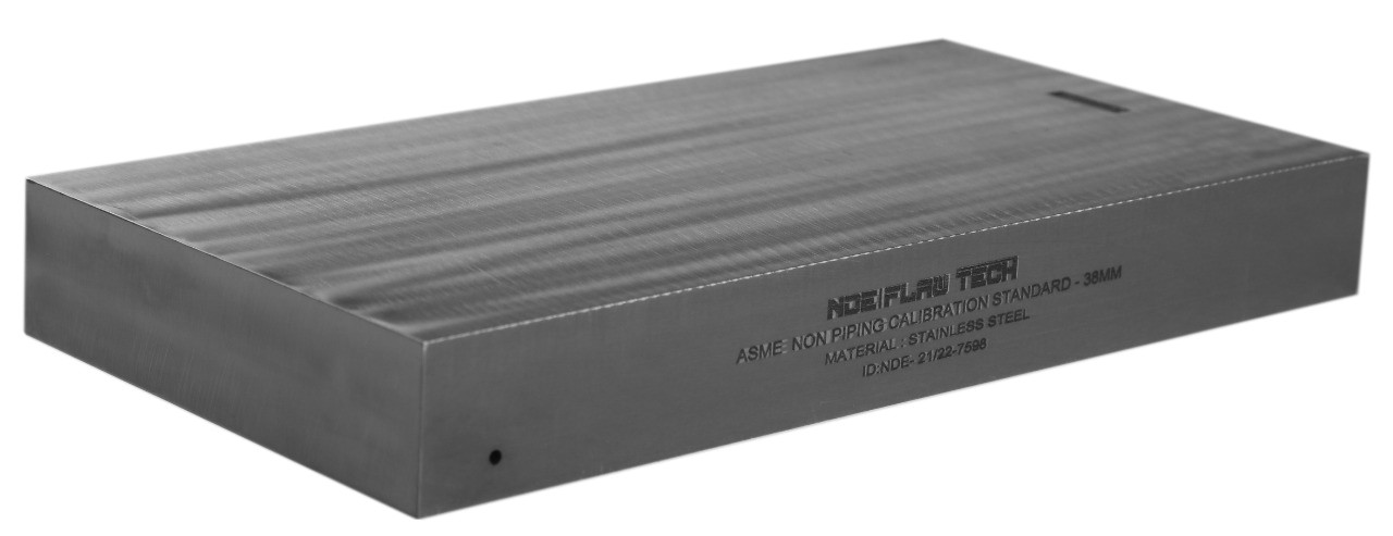
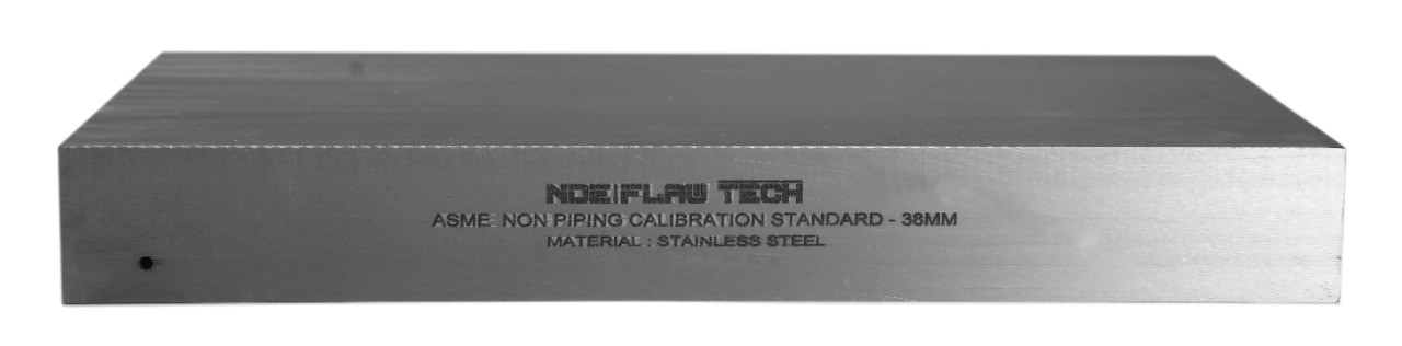
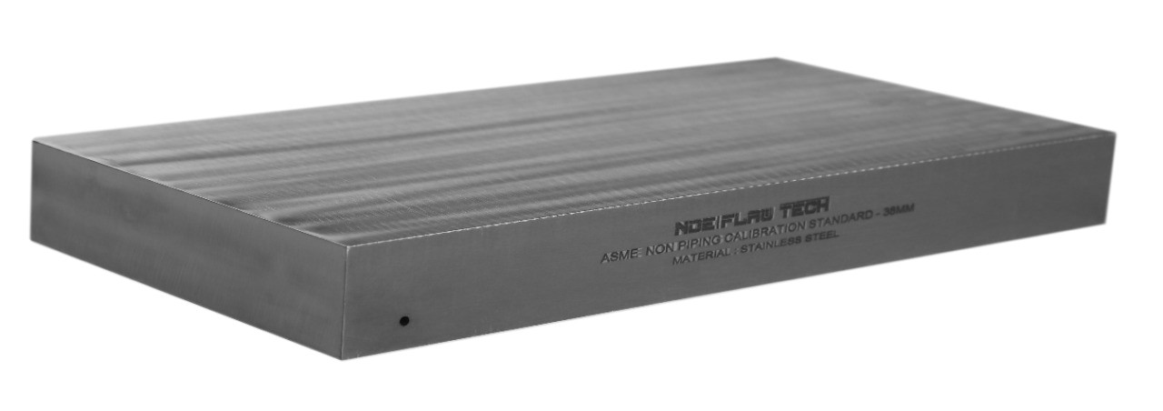
ASME Sec V Basic Calibration Block (38mm HALF SKIP WITHOUT NOTCH) METRIC VERSION
ASME Sec V Basic Calibration Block (38mm HALF SKIP WITHOUT NOTCH) METRIC VERSION This block can be used as a calibration block with a compression probe; however, its main use is as a reference block with either compression or shear wave probes. Its most common uses are for setting test sensitivity prior to inspection, using various depth of individual Side Drilled Holes (SDH) as reference reflectors. The test sensitivity as set by means of Distance amplitude Curve (DAC)/Time Correction Gain (TCG). The block size and reflector locations shall be adequate to perform calibrations for the beam angle(s) and distance range(s) to be used. The block thickness (T) shall be varying according to test object. Acoustic signals from the same reflecting surface will have different amplitudes at different distances from the transducer. Distance amplitude correction (DAC) provides a means of establishing a graphic ‘reference level sensitivity’ as a function of sweep distance on the A-scan display. The use of DAC allows signals reflected from similar discontinuities to be evaluated where signal attenuation as a function of depth has been correlated. Most often DAC will allow for loss in amplitude over material depth (time), graphically on the A-scan display but can also be done electronically by certain instruments. Because near field length and beam spread vary according to transducer size and frequency, and materials vary in attenuation and velocity, a DAC curve must be established for each different situation. DAC may be employed in both longitudinal and shear modes of operation as well as either contact or immersion inspection techniques. A distance amplitude correction curve is constructed from the peak amplitude responses from reflectors of equal area at different distances in the same material. A-scan echoes are displayed at their non-electronically compensated height and the peak amplitude of each signal is marked on the flaw detector screen or, preferably, on a transparent plastic sheet attached to the screen. Reference standards which incorporate side drilled holes (SDH), flat bottom holes (FBH), or notches whereby the reflectors are located at varying depths are commonly used. It is important to recognize that regardless of the type of reflector used, the size and shape of the reflector must be constant. Commercially available reference standards for constructing DAC include ASTM Distance/Area Amplitude and ASTM E1158 Distance Amplitude blocks, NAVSHIPS Test block, and ASME Basic Calibration Blocks Geometry: contains three side-drilled holes at 38mm deep minimum at Ø3mm diameter. Hole locations through the thickness are ¼, ½ and ¾T. In accordance with ASME Sec V Art. 4 Fig. T-434.2.1. Dimensions: 38mm thick x 80mm wide x 114mm long.
Inch Version
ASME Sec V Basic Calibration Block (1½ FULL SKIP WITH NOTCH INCH VERSION)
ASME Sec V Basic Calibration Block (1½" FULL SKIP WITH NOTCH) INCH VERSION This block can be used as a calibration block with a compression probe; however, its main use is as a reference block with either compression or shear wave probes. Its most common uses are for setting test sensitivity prior to inspection, using various depths of individual Side Drilled Holes (SDH) as reference reflectors. The test sensitivity as set by means of Distance amplitude Curve (DAC)/Time Correction Gain (TCG). The block size and reflector locations shall be adequate to perform calibrations for the beam angle(s) and distance range(s) to be used. The block thickness (T) shall be varying according to test object. Acoustic signals from the same reflecting surface will have different amplitudes at different distances from the transducer. Distance amplitude correction (DAC) provides a means of establishing a graphic ‘reference level sensitivity’ as a function of sweep distance on the A-scan display. The use of DAC allows signals reflected from similar discontinuities to be evaluated where signal attenuation as a function of depth has been correlated. Most often DAC will allow for loss in amplitude over material depth (time), graphically on the A-scan display but can also be done electronically by certain instruments. Because near field length and beam spread vary according to transducer size and frequency, and materials vary in attenuation and velocity, a DAC curve must be established for each different situation. DAC may be employed in both longitudinal and shear modes of operation as well as either contact or immersion inspection techniques. A distance amplitude correction curve is constructed from the peak amplitude responses from reflectors of equal area at different distances in the same material. A-scan echoes are displayed at their non-electronically compensated height and the peak amplitude of each signal is marked on the flaw detector screen or, preferably, on a transparent plastic sheet attached to the screen. Reference standards which incorporate side drilled holes (SDH), flat bottom holes (FBH), or notches whereby the reflectors are located at varying depths are commonly used. It is important to recognize that regardless of the type of reflector used, the size and shape of the reflector must be constant. Commercially available reference standards for constructing DAC include ASTM Distance/Area Amplitude and ASTM E1158 Distance Amplitude blocks, NAVSHIPS Test block, and ASME Basic Calibration Blocks Geometry: contains three side-drilled holes at 1.5" deep minimum at 1/8" diameter. Hole locations through the thickness are ¼, ½ and ¾T. Also contains two EDM notches measuring 2%T deep x 1/4" max wide x 1.0" long min. In accordance with ASME Sec V Art. 4 Fig. T-434.2.1. Dimensions: 1½" thick x 6" wide x 9½" long.
Metric Version
ASME Sec V Basic Calibration Block (38mm FULL SKIP WITH NOTCH) METRIC VERSION
ASME Sec V Basic Calibration Block (38mm FULL SKIP WITH NOTCH) METRIC VERSION This block can be used as a calibration block with a compression probe; however, its main use is as a reference block with either compression or shear wave probes. Its most common uses are for setting test sensitivity prior to inspection, using various depth of individual Side Drilled Holes (SDH) as reference reflectors. The test sensitivity as set by means of Distance amplitude Curve (DAC)/Time Correction Gain (TCG). The block size and reflector locations shall be adequate to perform calibrations for the beam angle(s) and distance range(s) to be used. The block thickness (T) shall be varying according to test object. Acoustic signals from the same reflecting surface will have different amplitudes at different distances from the transducer. Distance amplitude correction (DAC) provides a means of establishing a graphic ‘reference level sensitivity’ as a function of sweep distance on the A-scan display. The use of DAC allows signals reflected from similar discontinuities to be evaluated where signal attenuation as a function of depth has been correlated. Most often DAC will allow for loss in amplitude over material depth (time), graphically on the A-scan display but can also be done electronically by certain instruments. Because near field length and beam spread vary according to transducer size and frequency, and materials vary in attenuation and velocity, a DAC curve must be established for each different situation. DAC may be employed in both longitudinal and shear modes of operation as well as either contact or immersion inspection techniques. A distance amplitude correction curve is constructed from the peak amplitude responses from reflectors of equal area at different distances in the same material. A-scan echoes are displayed at their non-electronically compensated height and the peak amplitude of each signal is marked on the flaw detector screen or, preferably, on a transparent plastic sheet attached to the screen. Reference standards which incorporate side drilled holes (SDH), flat bottom holes (FBH), or notches whereby the reflectors are located at varying depths are commonly used. It is important to recognize that regardless of the type of reflector used, the size and shape of the reflector must be constant. Commercially available reference standards for constructing DAC include ASTM Distance/Area Amplitude and ASTM E1158 Distance Amplitude blocks, NAVSHIPS Test block, and ASME Basic Calibration Blocks Geometry: contains three side-drilled holes at 38mm deep minimum at Ø3mm diameter. Hole locations through the thickness are ¼, ½ and ¾T. Also contains two EDM notches measuring 2%T deep x 6mm max wide x 25mm long min. In accordance with ASME Sec V Art. 4 Fig. T-434.2.1. Dimensions: 38mm thick x 152mm wide x 240mm long.
Inch Version
ASME Sec V Basic Calibration Block (1½" FULL SKIP WITHOUT NOTCH) INCH VERSION
ASME Sec V Basic Calibration Block (1½" FULL SKIP WITHOUT NOTCH) INCH VERSION This block can be used as a calibration block with a compression probe; however, its main use is as a reference block with either compression or shear wave probes. Its most common uses are for setting test sensitivity prior to inspection, using various depth of individual Side Drilled Holes (SDH) as reference reflectors. The test sensitivity as set by means of Distance amplitude Curve (DAC)/Time Correction Gain (TCG). The block size and reflector locations shall be adequate to perform calibrations for the beam angle(s) and distance range(s) to be used. The block thickness (T) shall be varying according to test object. Acoustic signals from the same reflecting surface will have different amplitudes at different distances from the transducer. Distance amplitude correction (DAC) provides a means of establishing a graphic ‘reference level sensitivity’ as a function of sweep distance on the A-scan display. The use of DAC allows signals reflected from similar discontinuities to be evaluated where signal attenuation as a function of depth has been correlated. Most often DAC will allow for loss in amplitude over material depth (time), graphically on the A-scan display but can also be done electronically by certain instruments. Because near field length and beam spread vary according to transducer size and frequency, and materials vary in attenuation and velocity, a DAC curve must be established for each different situation. DAC may be employed in both longitudinal and shear modes of operation as well as either contact or immersion inspection techniques. A distance amplitude correction curve is constructed from the peak amplitude responses from reflectors of equal area at different distances in the same material. A-scan echoes are displayed at their non-electronically compensated height and the peak amplitude of each signal is marked on the flaw detector screen or, preferably, on a transparent plastic sheet attached to the screen. Reference standards which incorporate side drilled holes (SDH), flat bottom holes (FBH), or notches whereby the reflectors are located at varying depths are commonly used. It is important to recognize that regardless of the type of reflector used, the size and shape of the reflector must be constant. Commercially available reference standards for constructing DAC include ASTM Distance/Area Amplitude and ASTM E1158 Distance Amplitude blocks, NAVSHIPS Test block, and ASME Basic Calibration Blocks Geometry: contains three side-drilled holes at 1.5" deep minimum at 1/8" diameter. Hole locations through the thickness are ¼, ½ and ¾T. In accordance with ASME Sec V Art. 4 Fig. T-434.2.1. Dimensions: 1½" thick x 3¼" wide x 8½" long.
Metric Version
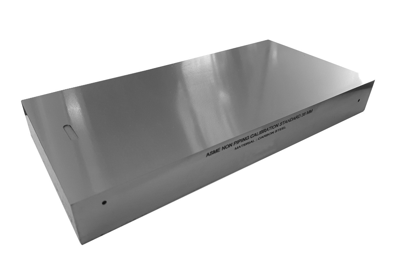
ASME Sec V Basic Calibration Block (38mm FULL SKIP WITHOUT NOTCH) METRIC VERSION
ASME Sec V Basic Calibration Block (38mm FULL SKIP WITHOUT NOTCH) METRIC VERSION This block can be used as a calibration block with a compression probe; however, its main use is as a reference block with either compression or shear wave probes. Its most common uses are for setting test sensitivity prior to inspection, using various depths of individual Side Drilled Holes (SDH) as reference reflectors. The test sensitivity as set by means of Distance amplitude Curve (DAC)/Time Correction Gain (TCG). The block size and reflector locations shall be adequate to perform calibrations for the beam angle(s) and distance range(s) to be used. The block thickness (T) shall be varying according to test object. Acoustic signals from the same reflecting surface will have different amplitudes at different distances from the transducer. Distance amplitude correction (DAC) provides a means of establishing a graphic ‘reference level sensitivity’ as a function of sweep distance on the A-scan display. The use of DAC allows signals reflected from similar discontinuities to be evaluated where signal attenuation as a function of depth has been correlated. Most often DAC will allow for loss in amplitude over material depth (time), graphically on the A-scan display but can also be done electronically by certain instruments. Because near field length and beam spread vary according to transducer size and frequency, and materials vary in attenuation and velocity, a DAC curve must be established for each different situation. DAC may be employed in both longitudinal and shear modes of operation as well as either contact or immersion inspection techniques. A distance amplitude correction curve is constructed from the peak amplitude responses from reflectors of equal area at different distances in the same material. A-scan echoes are displayed at their non-electronically compensated height and the peak amplitude of each signal is marked on the flaw detector screen or, preferably, on a transparent plastic sheet attached to the screen. Reference standards which incorporate side drilled holes (SDH), flat bottom holes (FBH), or notches whereby the reflectors are located at varying depths are commonly used. It is important to recognize that regardless of the type of reflector used, the size and shape of the reflector must be constant. Commercially available reference standards for constructing DAC include ASTM Distance/Area Amplitude and ASTM E1158 Distance Amplitude blocks, NAVSHIPS Test block, and ASME Basic Calibration Blocks Geometry: contains three side-drilled holes at 38mm deep minimum at Ø3mm diameter. Hole locations through the thickness are ¼, ½ and ¾T. In accordance with ASME Sec V Art. 4 Fig. T-434.2.1. Dimensions: 38mm thick x 80mm wide x 215mm long.
Inch Version
ASME Sec V Basic Calibration Block (1½" - 1½ SKIP WITH NOTCH) INCH VERSION
ASME Sec V Basic Calibration Block (1½" - 1½ SKIP WITH NOTCH) INCH VERSION This block can be used as a calibration block with a compression probe; however, its main use is as a reference block with either compression or shear wave probes. Its most common uses are for setting test sensitivity prior to inspection, using various depth of individual Side Drilled Holes (SDH) as reference reflectors. The test sensitivity as set by means of Distance amplitude Curve (DAC)/Time Correction Gain (TCG). The block size and reflector locations shall be adequate to perform calibrations for the beam angle(s) and distance range(s) to be used. The block thickness (T) shall be varying according to test object. Acoustic signals from the same reflecting surface will have different amplitudes at different distances from the transducer. Distance amplitude correction (DAC) provides a means of establishing a graphic ‘reference level sensitivity’ as a function of sweep distance on the A-scan display. The use of DAC allows signals reflected from similar discontinuities to be evaluated where signal attenuation as a function of depth has been correlated. Most often DAC will allow for loss in amplitude over material depth (time), graphically on the A-scan display but can also be done electronically by certain instruments. Because near field length and beam spread vary according to transducer size and frequency, and materials vary in attenuation and velocity, a DAC curve must be established for each different situation. DAC may be employed in both longitudinal and shear modes of operation as well as either contact or immersion inspection techniques. A distance amplitude correction curve is constructed from the peak amplitude responses from reflectors of equal area at different distances in the same material. A-scan echoes are displayed at their non-electronically compensated height and the peak amplitude of each signal is marked on the flaw detector screen or, preferably, on a transparent plastic sheet attached to the screen. Reference standards which incorporate side drilled holes (SDH), flat bottom holes (FBH), or notches whereby the reflectors are located at varying depths are commonly used. It is important to recognize that regardless of the type of reflector used, the size and shape of the reflector must be constant. Commercially available reference standards for constructing DAC include ASTM Distance/Area Amplitude and ASTM E1158 Distance Amplitude blocks, NAVSHIPS Test block, and ASME Basic Calibration Blocks Geometry: contains three side-drilled holes at 1.5" deep minimum at 1/8" diameter. Hole locations through the thickness are ¼, ½ and ¾T. Also contains two EDM notches measuring 2%T deep x 1/4" max wide x 1.0" long min. In accordance with ASME Sec V Art. 4 Fig. T-434.2.1. Dimensions: 1½" thick x 6" wide x 12½" long.
Metric Version
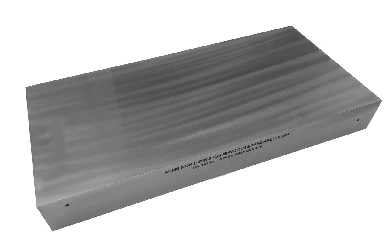
ASME Sec V Basic Calibration Block (38mm - 1½ SKIP WITH NOTCH) METRIC VERSION
ASME Sec V Basic Calibration Block (38mm - 1½ SKIP WITH NOTCH) METRIC VERSION This block can be used as a calibration block with a compression probe; however, its main use is as a reference block with either compression or shear wave probes. Its most common uses are for setting test sensitivity prior to inspection, using various depth of individual Side Drilled Holes (SDH) as reference reflectors. The test sensitivity as set by means of Distance amplitude Curve (DAC)/Time Correction Gain (TCG). The block size and reflector locations shall be adequate to perform calibrations for the beam angle(s) and distance range(s) to be used. The block thickness (T) shall be varying according to test object. Acoustic signals from the same reflecting surface will have different amplitudes at different distances from the transducer. Distance amplitude correction (DAC) provides a means of establishing a graphic ‘reference level sensitivity’ as a function of sweep distance on the A-scan display. The use of DAC allows signals reflected from similar discontinuities to be evaluated where signal attenuation as a function of depth has been correlated. Most often DAC will allow for loss in amplitude over material depth (time), graphically on the A-scan display but can also be done electronically by certain instruments. Because near field length and beam spread vary according to transducer size and frequency, and materials vary in attenuation and velocity, a DAC curve must be established for each different situation. DAC may be employed in both longitudinal and shear modes of operation as well as either contact or immersion inspection techniques. A distance amplitude correction curve is constructed from the peak amplitude responses from reflectors of equal area at different distances in the same material. A-scan echoes are displayed at their non-electronically compensated height and the peak amplitude of each signal is marked on the flaw detector screen or, preferably, on a transparent plastic sheet attached to the screen. Reference standards which incorporate side drilled holes (SDH), flat bottom holes (FBH), or notches whereby the reflectors are located at varying depths are commonly used. It is important to recognize that regardless of the type of reflector used, the size and shape of the reflector must be constant. Commercially available reference standards for constructing DAC include ASTM Distance/Area Amplitude and ASTM E1158 Distance Amplitude blocks, NAVSHIPS Test block, and ASME Basic Calibration Blocks Geometry: contains three side-drilled holes at 38mm deep minimum at Ø3mm diameter. Hole locations through the thickness are ¼, ½ and ¾T. Also contains two EDM notches measuring 2%T deep x 6mm max wide x 25mm long min. In accordance with ASME Sec V Art. 4 Fig. T-434.2.1. Dimensions: 38mm thick x 152mm wide x 320mm long.
Inch Version
ASME Sec V Basic Calibration Block (1½"- 1½ SKIP WITHOUT NOTCH) INCH VERSION
ASME Sec V Basic Calibration Block (1½"- 1½ SKIP WITHOUT NOTCH) INCH VERSION This block can be used as a calibration block with a compression probe; however, its main use is as a reference block with either compression or shear wave probes. Its most common uses are for setting test sensitivity prior to inspection, using various depth of individual Side Drilled Holes (SDH) as reference reflectors. The test sensitivity as set by means of Distance amplitude Curve (DAC)/Time Correction Gain (TCG). The block size and reflector locations shall be adequate to perform calibrations for the beam angle(s) and distance range(s) to be used. The block thickness (T) shall be varying according to test object. Acoustic signals from the same reflecting surface will have different amplitudes at different distances from the transducer. Distance amplitude correction (DAC) provides a means of establishing a graphic ‘reference level sensitivity’ as a function of sweep distance on the A-scan display. The use of DAC allows signals reflected from similar discontinuities to be evaluated where signal attenuation as a function of depth has been correlated. Most often DAC will allow for loss in amplitude over material depth (time), graphically on the A-scan display but can also be done electronically by certain instruments. Because near field length and beam spread vary according to transducer size and frequency, and materials vary in attenuation and velocity, a DAC curve must be established for each different situation. DAC may be employed in both longitudinal and shear modes of operation as well as either contact or immersion inspection techniques. A distance amplitude correction curve is constructed from the peak amplitude responses from reflectors of equal area at different distances in the same material. A-scan echoes are displayed at their non-electronically compensated height and the peak amplitude of each signal is marked on the flaw detector screen or, preferably, on a transparent plastic sheet attached to the screen. Reference standards which incorporate side drilled holes (SDH), flat bottom holes (FBH), or notches whereby the reflectors are located at varying depths are commonly used. It is important to recognize that regardless of the type of reflector used, the size and shape of the reflector must be constant. Commercially available reference standards for constructing DAC include ASTM Distance/Area Amplitude and ASTM E1158 Distance Amplitude blocks, NAVSHIPS Test block, and ASME Basic Calibration Blocks Geometry: contains three side-drilled holes at 1.5" deep minimum at 1/8" diameter. Hole locations through the thickness are ¼, ½ and ¾T. In accordance with ASME Sec V Art. 4 Fig. T-434.2.1. Dimensions: 1½" thick x 3¼" wide x 12½" long.
Metric Version
ASME Sec V Basic Calibration Block (38mm - 1½ SKIP WITHOUT NOTCH) METRIC VERSION
ASME Sec V Basic Calibration Block (38mm - 1½ SKIP WITHOUT NOTCH) METRIC VERSION This block can be used as a calibration block with a compression probe; however, its main use is as a reference block with either compression or shear wave probes. Its most common uses are for setting test sensitivity prior to inspection, using various depths of individual Side Drilled Holes (SDH) as reference reflectors. The test sensitivity as set by means of Distance amplitude Curve (DAC)/Time Correction Gain (TCG). The block size and reflector locations shall be adequate to perform calibrations for the beam angle(s) and distance range(s) to be used. The block thickness (T) shall be varying according to test object. Acoustic signals from the same reflecting surface will have different amplitudes at different distances from the transducer. Distance amplitude correction (DAC) provides a means of establishing a graphic ‘reference level sensitivity’ as a function of sweep distance on the A-scan display. The use of DAC allows signals reflected from similar discontinuities to be evaluated where signal attenuation as a function of depth has been correlated. Most often DAC will allow for loss in amplitude over material depth (time), graphically on the A-scan display but can also be done electronically by certain instruments. Because near field length and beam spread vary according to transducer size and frequency, and materials vary in attenuation and velocity, a DAC curve must be established for each different situation. DAC may be employed in both longitudinal and shear modes of operation as well as either contact or immersion inspection techniques. A distance amplitude correction curve is constructed from the peak amplitude responses from reflectors of equal area at different distances in the same material. A-scan echoes are displayed at their non-electronically compensated height and the peak amplitude of each signal is marked on the flaw detector screen or, preferably, on a transparent plastic sheet attached to the screen. Reference standards which incorporate side drilled holes (SDH), flat bottom holes (FBH), or notches whereby the reflectors are located at varying depths are commonly used. It is important to recognize that regardless of the type of reflector used, the size and shape of the reflector must be constant. Commercially available reference standards for constructing DAC include ASTM Distance/Area Amplitude and ASTM E1158 Distance Amplitude blocks, NAVSHIPS Test block, and ASME Basic Calibration Blocks Geometry: contains three side-drilled holes at 38mm deep minimum at Ø3mm diameter. Hole locations through the thickness are ¼, ½ and ¾T. In accordance with ASME Sec V Art. 4 Fig. T-434.2.1. Dimensions: 38mm thick x 80mm wide x 318mm long.
Inch Version
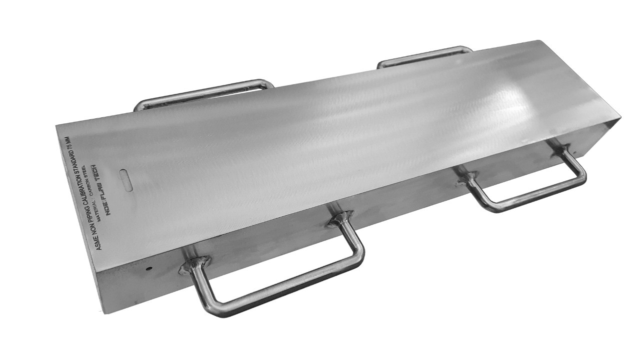
ASME Sec V Basic Calibration Block (3" HALF SKIP WITH NOTCH) INCH VERSION
ASME Sec V Basic Calibration Block (3" HALF SKIP WITH NOTCH) INCH VERSION This block can be used as a calibration block with a compression probe; however, its main use is as a reference block with either compression or shear wave probes. Its most common uses are for setting test sensitivity prior to inspection, using various depth of individual Side Drilled Holes (SDH) as reference reflectors. The test sensitivity as set by means of Distance amplitude Curve (DAC)/Time Correction Gain (TCG). The block size and reflector locations shall be adequate to perform calibrations for the beam angle(s) and distance range(s) to be used. The block thickness (T) shall be varying according to test object. Acoustic signals from the same reflecting surface will have different amplitudes at different distances from the transducer. Distance amplitude correction (DAC) provides a means of establishing a graphic ‘reference level sensitivity’ as a function of sweep distance on the A-scan display. The use of DAC allows signals reflected from similar discontinuities to be evaluated where signal attenuation as a function of depth has been correlated. Most often DAC will allow for loss in amplitude over material depth (time), graphically on the A-scan display but can also be done electronically by certain instruments. Because near field length and beam spread vary according to transducer size and frequency, and materials vary in attenuation and velocity, a DAC curve must be established for each different situation. DAC may be employed in both longitudinal and shear modes of operation as well as either contact or immersion inspection techniques. A distance amplitude correction curve is constructed from the peak amplitude responses from reflectors of equal area at different distances in the same material. A-scan echoes are displayed at their non-electronically compensated height and the peak amplitude of each signal is marked on the flaw detector screen or, preferably, on a transparent plastic sheet attached to the screen. Reference standards which incorporate side drilled holes (SDH), flat bottom holes (FBH), or notches whereby the reflectors are located at varying depths are commonly used. It is important to recognize that regardless of the type of reflector used, the size and shape of the reflector must be constant. Commercially available reference standards for constructing DAC include ASTM Distance/Area Amplitude and ASTM E1158 Distance Amplitude blocks, NAVSHIPS Test block, and ASME Basic Calibration Blocks Geometry: contains three side-drilled holes at 1.5" deep minimum at 3/16" diameter. Hole locations through the thickness are ¼, ½ and ¾T. Also contains two EDM notches measuring 2%T deep x 1/4" max wide x 1.0" long min. In accordance with ASME Sec V Art. 4 Fig. T-434.2.1. Dimensions: 3" thick x 6" wide x 17¾" long.
Metric Version

ASME Sec V Basic Calibration Block (75mm HALF SKIP WITH NOTCH) METRIC VERSION
ASME Sec V Basic Calibration Block (75mm HALF SKIP WITH NOTCH) METRIC VERSION This block can be used as a calibration block with a compression probe; however, its main use is as a reference block with either compression or shear wave probes. Its most common uses are for setting test sensitivity prior to inspection, using various depth of individual Side Drilled Holes (SDH) as reference reflectors. The test sensitivity as set by means of Distance amplitude Curve (DAC)/Time Correction Gain (TCG). The block size and reflector locations shall be adequate to perform calibrations for the beam angle(s) and distance range(s) to be used. The block thickness (T) shall be varying according to test object. Acoustic signals from the same reflecting surface will have different amplitudes at different distances from the transducer. Distance amplitude correction (DAC) provides a means of establishing a graphic ‘reference level sensitivity’ as a function of sweep distance on the A-scan display. The use of DAC allows signals reflected from similar discontinuities to be evaluated where signal attenuation as a function of depth has been correlated. Most often DAC will allow for loss in amplitude over material depth (time), graphically on the A-scan display but can also be done electronically by certain instruments. Because near field length and beam spread vary according to transducer size and frequency, and materials vary in attenuation and velocity, a DAC curve must be established for each different situation. DAC may be employed in both longitudinal and shear modes of operation as well as either contact or immersion inspection techniques. A distance amplitude correction curve is constructed from the peak amplitude responses from reflectors of equal area at different distances in the same material. A-scan echoes are displayed at their non-electronically compensated height and the peak amplitude of each signal is marked on the flaw detector screen or, preferably, on a transparent plastic sheet attached to the screen. Reference standards which incorporate side drilled holes (SDH), flat bottom holes (FBH), or notches whereby the reflectors are located at varying depths are commonly used. It is important to recognize that regardless of the type of reflector used, the size and shape of the reflector must be constant. Commercially available reference standards for constructing DAC include ASTM Distance/Area Amplitude and ASTM E1158 Distance Amplitude blocks, NAVSHIPS Test block, and ASME Basic Calibration Blocks Geometry: contains three side-drilled holes at 38mm deep minimum at Ø5mm diameter. Hole locations through the thickness are ¼, ½ and ¾T. Also contains two EDM notches measuring 2%T deep x 6mm max wide x 25mm long min. In accordance with ASME Sec V Art. 4 Fig. T-434.2.1. Dimensions: 75mm thick x 152mm wide x 450mm long.
Inch Version
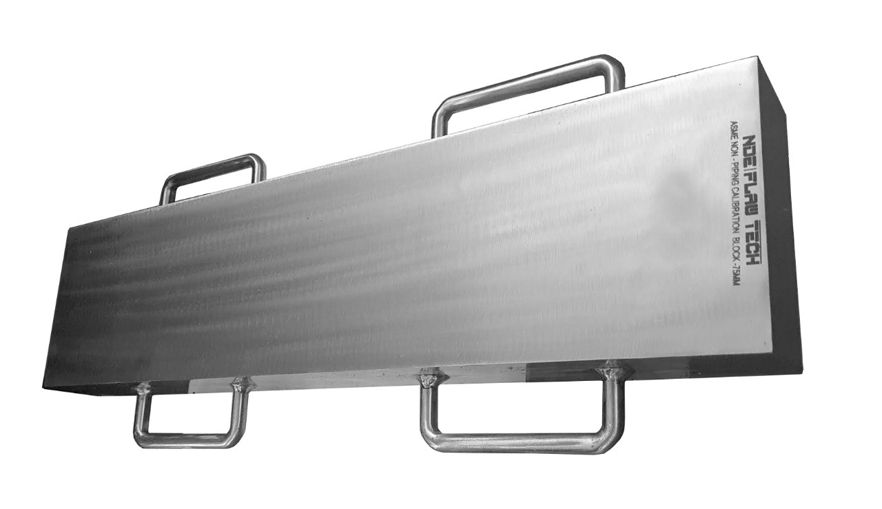
ASME Sec V Basic Calibration Block (3
ASME Sec V Basic Calibration Block (3" HALF SKIP WITHOUT NOTCH) INCH VERSION This block can be used as a calibration block with a compression probe; however, its main use is as a reference block with either compression or shear wave probes. Its most common uses are for setting test sensitivity prior to inspection, using various depth of individual Side Drilled Holes (SDH) as reference reflectors. The test sensitivity as set by means of Distance amplitude Curve (DAC)/Time Correction Gain (TCG). The block size and reflector locations shall be adequate to perform calibrations for the beam angle(s) and distance range(s) to be used. The block thickness (T) shall be varying according to test object. Acoustic signals from the same reflecting surface will have different amplitudes at different distances from the transducer. Distance amplitude correction (DAC) provides a means of establishing a graphic ‘reference level sensitivity’ as a function of sweep distance on the A-scan display. The use of DAC allows signals reflected from similar discontinuities to be evaluated where signal attenuation as a function of depth has been correlated. Most often DAC will allow for loss in amplitude over material depth (time), graphically on the A-scan display but can also be done electronically by certain instruments. Because near field length and beam spread vary according to transducer size and frequency, and materials vary in attenuation and velocity, a DAC curve must be established for each different situation. DAC may be employed in both longitudinal and shear modes of operation as well as either contact or immersion inspection techniques. A distance amplitude correction curve is constructed from the peak amplitude responses from reflectors of equal area at different distances in the same material. A-scan echoes are displayed at their non-electronically compensated height and the peak amplitude of each signal is marked on the flaw detector screen or, preferably, on a transparent plastic sheet attached to the screen. Reference standards which incorporate side drilled holes (SDH), flat bottom holes (FBH), or notches whereby the reflectors are located at varying depths are commonly used. It is important to recognize that regardless of the type of reflector used, the size and shape of the reflector must be constant. Commercially available reference standards for constructing DAC include ASTM Distance/Area Amplitude and ASTM E1158 Distance Amplitude blocks, NAVSHIPS Test block, and ASME Basic Calibration Blocks Geometry: contains three side-drilled holes at 1.5" deep minimum at 3/16" diameter. Hole locations through the thickness are ¼, ½ and ¾T. In accordance with ASME Sec V Art. 4 Fig. T-434.2.1. Dimensions: 3" thick x 3¼" wide x 7½" long.
Metric Version
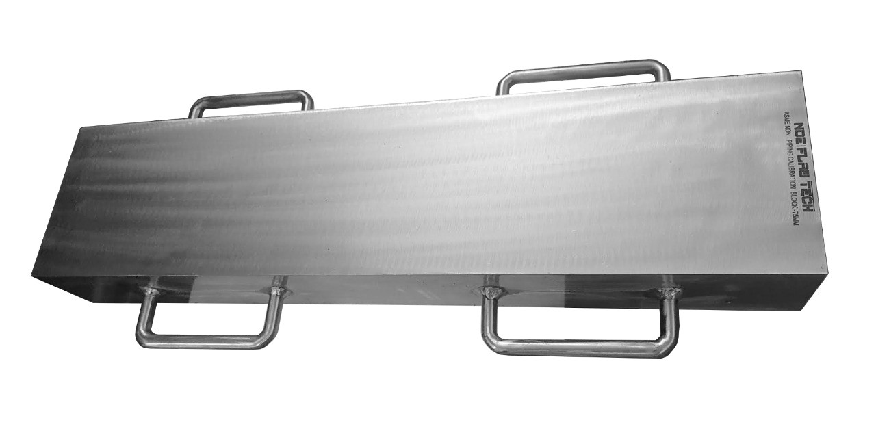
ASME Sec V Basic Calibration Block (75mm HALF SKIP WITHOUT NOTCH) METRIC VERSION
ASME Sec V Basic Calibration Block (75mm HALF SKIP WITHOUT NOTCH) METRIC VERSION This block can be used as a calibration block with a compression probe; however, its main use is as a reference block with either compression or shear wave probes. Its most common uses are for setting test sensitivity prior to inspection, using various depth of individual Side Drilled Holes (SDH) as reference reflectors. The test sensitivity as set by means of Distance amplitude Curve (DAC)/Time Correction Gain (TCG). The block size and reflector locations shall be adequate to perform calibrations for the beam angle(s) and distance range(s) to be used. The block thickness (T) shall be varying according to test object. Acoustic signals from the same reflecting surface will have different amplitudes at different distances from the transducer. Distance amplitude correction (DAC) provides a means of establishing a graphic ‘reference level sensitivity’ as a function of sweep distance on the A-scan display. The use of DAC allows signals reflected from similar discontinuities to be evaluated where signal attenuation as a function of depth has been correlated. Most often DAC will allow for loss in amplitude over material depth (time), graphically on the A-scan display but can also be done electronically by certain instruments. Because near field length and beam spread vary according to transducer size and frequency, and materials vary in attenuation and velocity, a DAC curve must be established for each different situation. DAC may be employed in both longitudinal and shear modes of operation as well as either contact or immersion inspection techniques. A distance amplitude correction curve is constructed from the peak amplitude responses from reflectors of equal area at different distances in the same material. A-scan echoes are displayed at their non-electronically compensated height and the peak amplitude of each signal is marked on the flaw detector screen or, preferably, on a transparent plastic sheet attached to the screen. Reference standards which incorporate side drilled holes (SDH), flat bottom holes (FBH), or notches whereby the reflectors are located at varying depths are commonly used. It is important to recognize that regardless of the type of reflector used, the size and shape of the reflector must be constant. Commercially available reference standards for constructing DAC include ASTM Distance/Area Amplitude and ASTM E1158 Distance Amplitude blocks, NAVSHIPS Test block, and ASME Basic Calibration Blocks Geometry: contains three side-drilled holes at 38mm deep minimum at Ø5mm diameter. Hole locations through the thickness are ¼, ½ and ¾T. In accordance with ASME Sec V Art. 4 Fig. T-434.2.1. Dimensions: 75mm thick x 80mm wide x 190mm long.
Inch Version
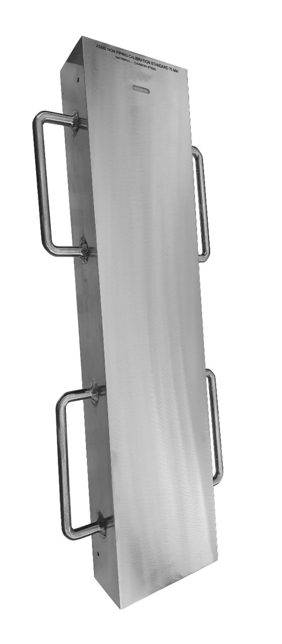
ASME Sec V Basic Calibration Block (3
ASME Sec V Basic Calibration Block (3" FULL SKIP WITH NOTCH) INCH VERSION This block can be used as a calibration block with a compression probe; however, its main use is as a reference block with either compression or shear wave probes. Its most common uses are for setting test sensitivity prior to inspection, using various depth of individual Side Drilled Holes (SDH) as reference reflectors. The test sensitivity as set by means of Distance amplitude Curve (DAC)/Time Correction Gain (TCG). The block size and reflector locations shall be adequate to perform calibrations for the beam angle(s) and distance range(s) to be used. The block thickness (T) shall be varying according to test object. Acoustic signals from the same reflecting surface will have different amplitudes at different distances from the transducer. Distance amplitude correction (DAC) provides a means of establishing a graphic ‘reference level sensitivity’ as a function of sweep distance on the A-scan display. The use of DAC allows signals reflected from similar discontinuities to be evaluated where signal attenuation as a function of depth has been correlated. Most often DAC will allow for loss in amplitude over material depth (time), graphically on the A-scan display but can also be done electronically by certain instruments. Because near field length and beam spread vary according to transducer size and frequency, and materials vary in attenuation and velocity, a DAC curve must be established for each different situation. DAC may be employed in both longitudinal and shear modes of operation as well as either contact or immersion inspection techniques. A distance amplitude correction curve is constructed from the peak amplitude responses from reflectors of equal area at different distances in the same material. A-scan echoes are displayed at their non-electronically compensated height and the peak amplitude of each signal is marked on the flaw detector screen or, preferably, on a transparent plastic sheet attached to the screen. Reference standards which incorporate side drilled holes (SDH), flat bottom holes (FBH), or notches whereby the reflectors are located at varying depths are commonly used. It is important to recognize that regardless of the type of reflector used, the size and shape of the reflector must be constant. Commercially available reference standards for constructing DAC include ASTM Distance/Area Amplitude and ASTM E1158 Distance Amplitude blocks, NAVSHIPS Test block, and ASME Basic Calibration Blocks Geometry: contains three side-drilled holes at 1.5" deep minimum at 3/16" diameter. Hole locations through the thickness are ¼, ½ and ¾T. Also contains two EDM notches measuring 2%T deep x 1/4" max wide x 1.0" long min. In accordance with ASME Sec V Art. 4 Fig. T-434.2.1. Dimensions: 3" thick x 6" wide x 17¾" long.
Metric Version
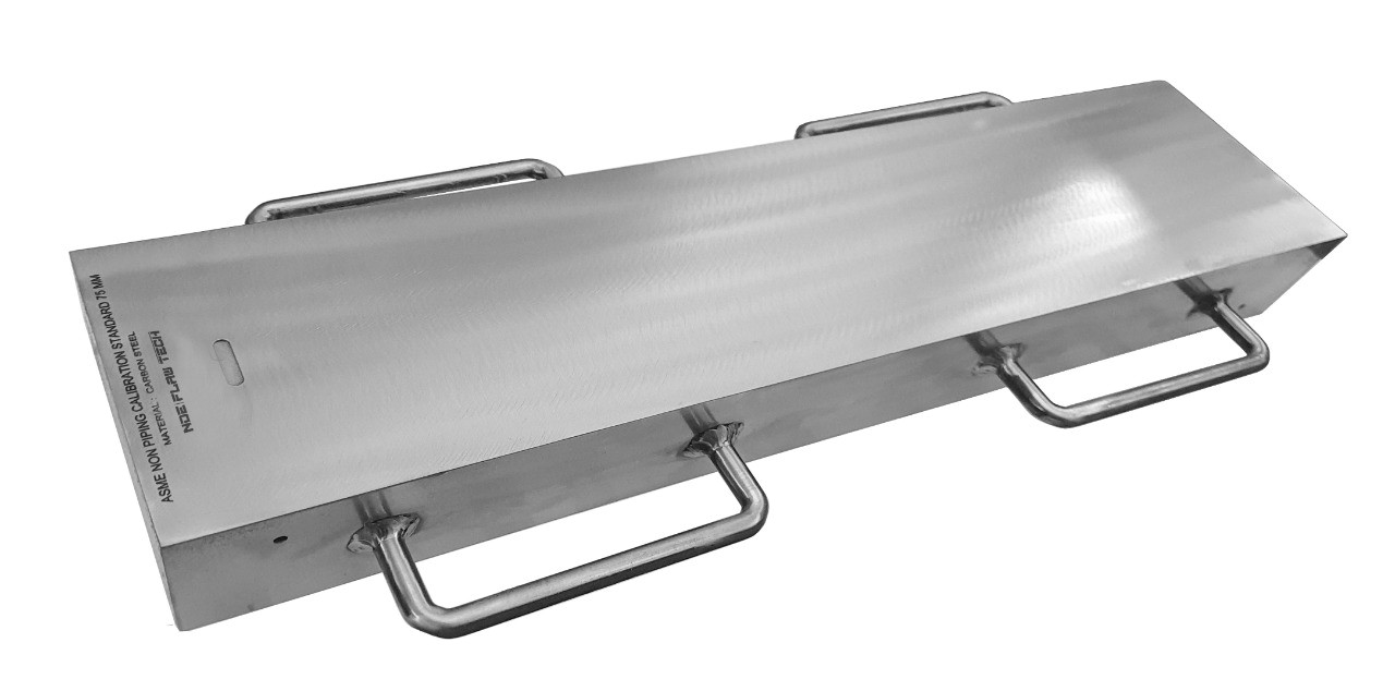
ASME Sec V Basic Calibration Block (75mm FULL SKIP WITH NOTCH) METRIC VERSION
ASME Sec V Basic Calibration Block (75mm FULL SKIP WITH NOTCH) METRIC VERSION This block can be used as a calibration block with a compression probe; however, its main use is as a reference block with either compression or shear wave probes. Its most common uses are for setting test sensitivity prior to inspection, using various depth of individual Side Drilled Holes (SDH) as reference reflectors. The test sensitivity as set by means of Distance amplitude Curve (DAC)/Time Correction Gain (TCG). The block size and reflector locations shall be adequate to perform calibrations for the beam angle(s) and distance range(s) to be used. The block thickness (T) shall be varying according to test object. Acoustic signals from the same reflecting surface will have different amplitudes at different distances from the transducer. Distance amplitude correction (DAC) provides a means of establishing a graphic ‘reference level sensitivity’ as a function of sweep distance on the A-scan display. The use of DAC allows signals reflected from similar discontinuities to be evaluated where signal attenuation as a function of depth has been correlated. Most often DAC will allow for loss in amplitude over material depth (time), graphically on the A-scan display but can also be done electronically by certain instruments. Because near field length and beam spread vary according to transducer size and frequency, and materials vary in attenuation and velocity, a DAC curve must be established for each different situation. DAC may be employed in both longitudinal and shear modes of operation as well as either contact or immersion inspection techniques. A distance amplitude correction curve is constructed from the peak amplitude responses from reflectors of equal area at different distances in the same material. A-scan echoes are displayed at their non-electronically compensated height and the peak amplitude of each signal is marked on the flaw detector screen or, preferably, on a transparent plastic sheet attached to the screen. Reference standards which incorporate side drilled holes (SDH), flat bottom holes (FBH), or notches whereby the reflectors are located at varying depths are commonly used. It is important to recognize that regardless of the type of reflector used, the size and shape of the reflector must be constant. Commercially available reference standards for constructing DAC include ASTM Distance/Area Amplitude and ASTM E1158 Distance Amplitude blocks, NAVSHIPS Test block, and ASME Basic Calibration Blocks Geometry: contains three side-drilled holes at 38mm deep minimum at Ø5mm diameter. Hole locations through the thickness are ¼, ½ and ¾T. Also contains two EDM notches measuring 2%T deep x 6mm max wide x 25mm long min. In accordance with ASME Sec V Art. 4 Fig. T-434.2.1. Dimensions: 75mm thick x 152mm wide x 450mm long.
Inch Version
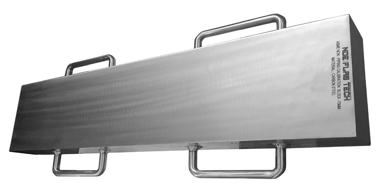
ASME Sec V Basic Calibration Block (3" FULL SKIP WITHOUT NOTCH) INCH VERSION
ASME Sec V Basic Calibration Block (3" FULL SKIP WITHOUT NOTCH) INCH VERSION This block can be used as a calibration block with a compression probe; however, its main use is as a reference block with either compression or shear wave probes. Its most common uses are for setting test sensitivity prior to inspection, using various depth of individual Side Drilled Holes (SDH) as reference reflectors. The test sensitivity as set by means of Distance amplitude Curve (DAC)/Time Correction Gain (TCG). The block size and reflector locations shall be adequate to perform calibrations for the beam angle(s) and distance range(s) to be used. The block thickness (T) shall be varying according to test object. Acoustic signals from the same reflecting surface will have different amplitudes at different distances from the transducer. Distance amplitude correction (DAC) provides a means of establishing a graphic ‘reference level sensitivity’ as a function of sweep distance on the A-scan display. The use of DAC allows signals reflected from similar discontinuities to be evaluated where signal attenuation as a function of depth has been correlated. Most often DAC will allow for loss in amplitude over material depth (time), graphically on the A-scan display but can also be done electronically by certain instruments. Because near field length and beam spread vary according to transducer size and frequency, and materials vary in attenuation and velocity, a DAC curve must be established for each different situation. DAC may be employed in both longitudinal and shear modes of operation as well as either contact or immersion inspection techniques. A distance amplitude correction curve is constructed from the peak amplitude responses from reflectors of equal area at different distances in the same material. A-scan echoes are displayed at their non-electronically compensated height and the peak amplitude of each signal is marked on the flaw detector screen or, preferably, on a transparent plastic sheet attached to the screen. Reference standards which incorporate side drilled holes (SDH), flat bottom holes (FBH), or notches whereby the reflectors are located at varying depths are commonly used. It is important to recognize that regardless of the type of reflector used, the size and shape of the reflector must be constant. Commercially available reference standards for constructing DAC include ASTM Distance/Area Amplitude and ASTM E1158 Distance Amplitude blocks, NAVSHIPS Test block, and ASME Basic Calibration Blocks Geometry: contains three side-drilled holes at 1.5" deep minimum at 3/16" diameter. Hole locations through the thickness are ¼, ½ and ¾T. In accordance with ASME Sec V Art. 4 Fig. T-434.2.1. Dimensions: 3" thick x 3¼" wide x 15¾" long.
Metric Version
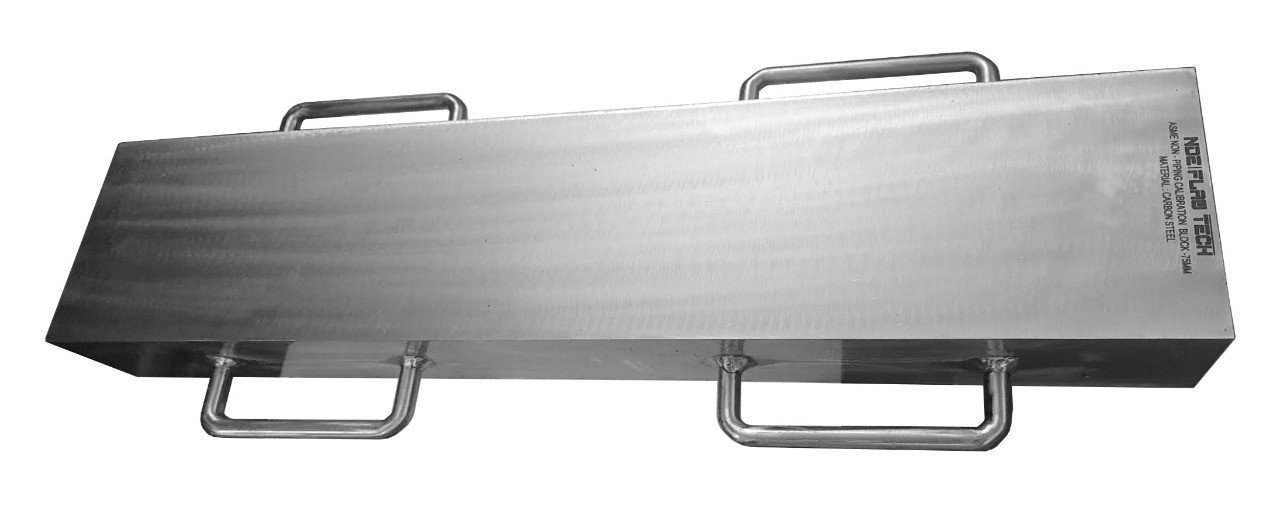
ASME Sec V Basic Calibration Block (75mm FULL SKIP WITHOUT NOTCH) METRIC VERSION
ASME Sec V Basic Calibration Block (75mm FULL SKIP WITHOUT NOTCH) METRIC VERSION This block can be used as a calibration block with a compression probe; however, its main use is as a reference block with either compression or shear wave probes. Its most common uses are for setting test sensitivity prior to inspection, using various depths of individual Side Drilled Holes (SDH) as reference reflectors. The test sensitivity as set by means of Distance amplitude Curve (DAC)/Time Correction Gain (TCG). The block size and reflector locations shall be adequate to perform calibrations for the beam angle(s) and distance range(s) to be used. The block thickness (T) shall be varying according to test object. Acoustic signals from the same reflecting surface will have different amplitudes at different distances from the transducer. Distance amplitude correction (DAC) provides a means of establishing a graphic ‘reference level sensitivity’ as a function of sweep distance on the A-scan display. The use of DAC allows signals reflected from similar discontinuities to be evaluated where signal attenuation as a function of depth has been correlated. Most often DAC will allow for loss in amplitude over material depth (time), graphically on the A-scan display but can also be done electronically by certain instruments. Because near field length and beam spread vary according to transducer size and frequency, and materials vary in attenuation and velocity, a DAC curve must be established for each different situation. DAC may be employed in both longitudinal and shear modes of operation as well as either contact or immersion inspection techniques. A distance amplitude correction curve is constructed from the peak amplitude responses from reflectors of equal area at different distances in the same material. A-scan echoes are displayed at their non-electronically compensated height and the peak amplitude of each signal is marked on the flaw detector screen or, preferably, on a transparent plastic sheet attached to the screen. Reference standards which incorporate side drilled holes (SDH), flat bottom holes (FBH), or notches whereby the reflectors are located at varying depths are commonly used. It is important to recognize that regardless of the type of reflector used, the size and shape of the reflector must be constant. Commercially available reference standards for constructing DAC include ASTM Distance/Area Amplitude and ASTM E1158 Distance Amplitude blocks, NAVSHIPS Test block, and ASME Basic Calibration Blocks Geometry: contains three side-drilled holes at 38mm deep minimum at Ø5mm diameter. Hole locations through the thickness are ¼, ½ and ¾T. In accordance with ASME Sec V Art. 4 Fig. T-434.2.1. Dimensions: 75mm thick x 80mm wide x 400mm long.
Inch Version
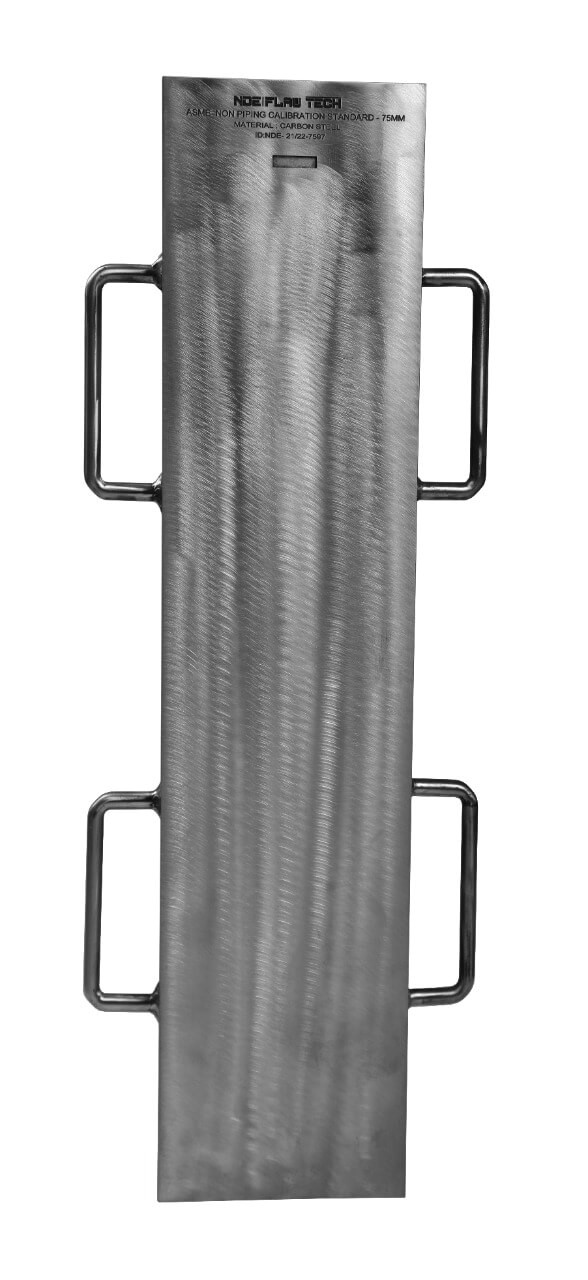
ASME Sec V Basic Calibration Block (3" - 1½ SKIP WITH NOTCH) INCH VERSION
ASME Sec V Basic Calibration Block (3" - 1½ SKIP WITH NOTCH) INCH VERSION This block can be used as a calibration block with a compression probe; however, its main use is as a reference block with either compression or shear wave probes. Its most common uses are for setting test sensitivity prior to inspection, using various depth of individual Side Drilled Holes (SDH) as reference reflectors. The test sensitivity as set by means of Distance amplitude Curve (DAC)/Time Correction Gain (TCG). The block size and reflector locations shall be adequate to perform calibrations for the beam angle(s) and distance range(s) to be used. The block thickness (T) shall be varying according to test object. Acoustic signals from the same reflecting surface will have different amplitudes at different distances from the transducer. Distance amplitude correction (DAC) provides a means of establishing a graphic ‘reference level sensitivity’ as a function of sweep distance on the A-scan display. The use of DAC allows signals reflected from similar discontinuities to be evaluated where signal attenuation as a function of depth has been correlated. Most often DAC will allow for loss in amplitude over material depth (time), graphically on the A-scan display but can also be done electronically by certain instruments. Because near field length and beam spread vary according to transducer size and frequency, and materials vary in attenuation and velocity, a DAC curve must be established for each different situation. DAC may be employed in both longitudinal and shear modes of operation as well as either contact or immersion inspection techniques. A distance amplitude correction curve is constructed from the peak amplitude responses from reflectors of equal area at different distances in the same material. A-scan echoes are displayed at their non-electronically compensated height and the peak amplitude of each signal is marked on the flaw detector screen or, preferably, on a transparent plastic sheet attached to the screen. Reference standards which incorporate side drilled holes (SDH), flat bottom holes (FBH), or notches whereby the reflectors are located at varying depths are commonly used. It is important to recognize that regardless of the type of reflector used, the size and shape of the reflector must be constant. Commercially available reference standards for constructing DAC include ASTM Distance/Area Amplitude and ASTM E1158 Distance Amplitude blocks, NAVSHIPS Test block, and ASME Basic Calibration Blocks Geometry: contains three side-drilled holes at 1.5" deep minimum at 3/16" diameter. Hole locations through the thickness are ¼, ½ and ¾T. Also contains two EDM notches measuring 2%T deep x 1/4" max wide x 1.0" long min. In accordance with ASME Sec V Art. 4 Fig. T-434.2.1. Dimensions: 3" thick x 6" wide x 24½" long.
Metric Version
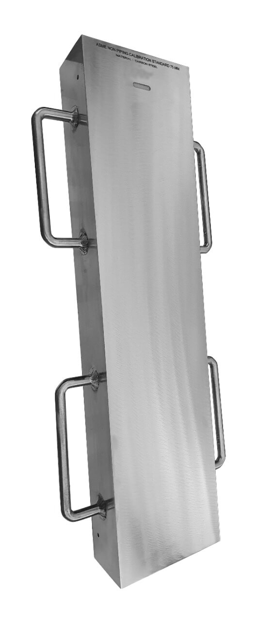
ASME Sec V Basic Calibration Block (75mm - 1½ SKIP WITH NOTCH) METRIC VERSION
ASME Sec V Basic Calibration Block (75mm - 1½ SKIP WITH NOTCH) METRIC VERSION This block can be used as a calibration block with a compression probe; however, its main use is as a reference block with either compression or shear wave probes. Its most common uses are for setting test sensitivity prior to inspection, using various depth of individual Side Drilled Holes (SDH) as reference reflectors. The test sensitivity as set by means of Distance amplitude Curve (DAC)/Time Correction Gain (TCG). The block size and reflector locations shall be adequate to perform calibrations for the beam angle(s) and distance range(s) to be used. The block thickness (T) shall be varying according to test object. Acoustic signals from the same reflecting surface will have different amplitudes at different distances from the transducer. Distance amplitude correction (DAC) provides a means of establishing a graphic ‘reference level sensitivity’ as a function of sweep distance on the A-scan display. The use of DAC allows signals reflected from similar discontinuities to be evaluated where signal attenuation as a function of depth has been correlated. Most often DAC will allow for loss in amplitude over material depth (time), graphically on the A-scan display but can also be done electronically by certain instruments. Because near field length and beam spread vary according to transducer size and frequency, and materials vary in attenuation and velocity, a DAC curve must be established for each different situation. DAC may be employed in both longitudinal and shear modes of operation as well as either contact or immersion inspection techniques. A distance amplitude correction curve is constructed from the peak amplitude responses from reflectors of equal area at different distances in the same material. A-scan echoes are displayed at their non-electronically compensated height and the peak amplitude of each signal is marked on the flaw detector screen or, preferably, on a transparent plastic sheet attached to the screen. Reference standards which incorporate side drilled holes (SDH), flat bottom holes (FBH), or notches whereby the reflectors are located at varying depths are commonly used. It is important to recognize that regardless of the type of reflector used, the size and shape of the reflector must be constant. Commercially available reference standards for constructing DAC include ASTM Distance/Area Amplitude and ASTM E1158 Distance Amplitude blocks, NAVSHIPS Test block, and ASME Basic Calibration Blocks Geometry: contains three side-drilled holes at 38mm deep minimum at Ø5mm diameter. Hole locations through the thickness are ¼, ½ and ¾T. Also contains two EDM notches measuring 2%T deep x 6mm max wide x 25mm long min. In accordance with ASME Sec V Art. 4 Fig. T-434.2.1. Dimensions: 75mm thick x 152mm wide x 620mm long.
Inch Version
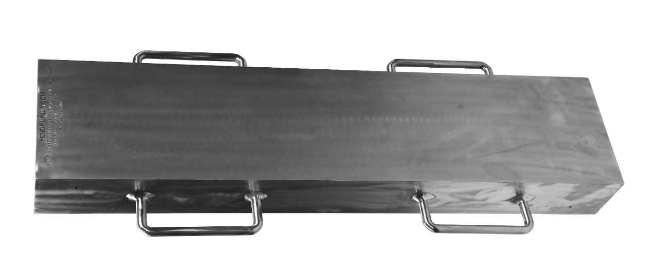
ASME Sec V Basic Calibration Block (3"- 1½ SKIP WITHOUT NOTCH) INCH VERSION
ASME Sec V Basic Calibration Block (3"- 1½ SKIP WITHOUT NOTCH) INCH VERSION This block can be used as a calibration block with a compression probe; however, its main use is as a reference block with either compression or shear wave probes. Its most common uses are for setting test sensitivity prior to inspection, using various depth of individual Side Drilled Holes (SDH) as reference reflectors. The test sensitivity as set by means of Distance amplitude Curve (DAC)/Time Correction Gain (TCG). The block size and reflector locations shall be adequate to perform calibrations for the beam angle(s) and distance range(s) to be used. The block thickness (T) shall be varying according to test object. Acoustic signals from the same reflecting surface will have different amplitudes at different distances from the transducer. Distance amplitude correction (DAC) provides a means of establishing a graphic ‘reference level sensitivity’ as a function of sweep distance on the A-scan display. The use of DAC allows signals reflected from similar discontinuities to be evaluated where signal attenuation as a function of depth has been correlated. Most often DAC will allow for loss in amplitude over material depth (time), graphically on the A-scan display but can also be done electronically by certain instruments. Because near field length and beam spread vary according to transducer size and frequency, and materials vary in attenuation and velocity, a DAC curve must be established for each different situation. DAC may be employed in both longitudinal and shear modes of operation as well as either contact or immersion inspection techniques. A distance amplitude correction curve is constructed from the peak amplitude responses from reflectors of equal area at different distances in the same material. A-scan echoes are displayed at their non-electronically compensated height and the peak amplitude of each signal is marked on the flaw detector screen or, preferably, on a transparent plastic sheet attached to the screen. Reference standards which incorporate side drilled holes (SDH), flat bottom holes (FBH), or notches whereby the reflectors are located at varying depths are commonly used. It is important to recognize that regardless of the type of reflector used, the size and shape of the reflector must be constant. Commercially available reference standards for constructing DAC include ASTM Distance/Area Amplitude and ASTM E1158 Distance Amplitude blocks, NAVSHIPS Test block, and ASME Basic Calibration Blocks Geometry: contains three side-drilled holes at 1.5" deep minimum at 3/16" diameter. Hole locations through the thickness are ¼, ½ and ¾T. In accordance with ASME Sec V Art. 4 Fig. T-434.2.1. Dimensions: 3" thick x 3¼" wide x 24½" long.
Metric Version
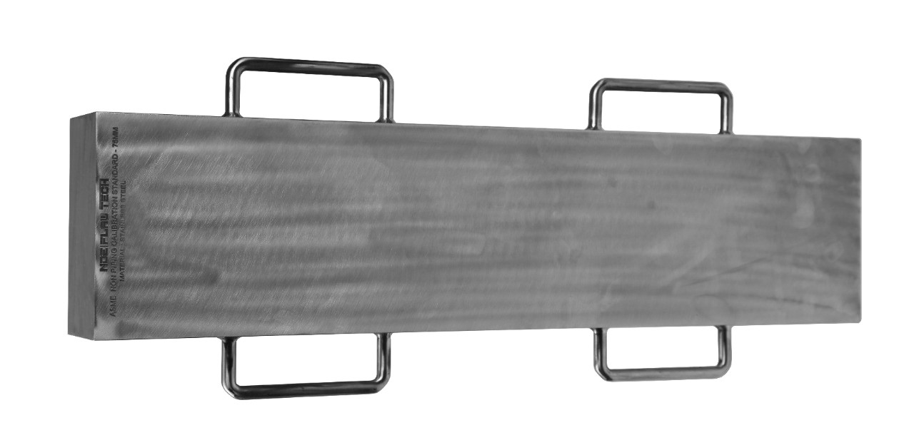
ASME Sec V Basic Calibration Block (75mm - 1½ SKIP WITHOUT NOTCH) METRIC VERSION
ASME Sec V Basic Calibration Block (75mm - 1½ SKIP WITHOUT NOTCH) METRIC VERSION This block can be used as a calibration block with a compression probe; however, its main use is as a reference block with either compression or shear wave probes. Its most common uses are for setting test sensitivity prior to inspection, using various depths of individual Side Drilled Holes (SDH) as reference reflectors. The test sensitivity as set by means of Distance amplitude Curve (DAC)/Time Correction Gain (TCG). The block size and reflector locations shall be adequate to perform calibrations for the beam angle(s) and distance range(s) to be used. The block thickness (T) shall be varying according to test object. Acoustic signals from the same reflecting surface will have different amplitudes at different distances from the transducer. Distance amplitude correction (DAC) provides a means of establishing a graphic ‘reference level sensitivity’ as a function of sweep distance on the A-scan display. The use of DAC allows signals reflected from similar discontinuities to be evaluated where signal attenuation as a function of depth has been correlated. Most often DAC will allow for loss in amplitude over material depth (time), graphically on the A-scan display but can also be done electronically by certain instruments. Because near field length and beam spread vary according to transducer size and frequency, and materials vary in attenuation and velocity, a DAC curve must be established for each different situation. DAC may be employed in both longitudinal and shear modes of operation as well as either contact or immersion inspection techniques. A distance amplitude correction curve is constructed from the peak amplitude responses from reflectors of equal area at different distances in the same material. A-scan echoes are displayed at their non-electronically compensated height and the peak amplitude of each signal is marked on the flaw detector screen or, preferably, on a transparent plastic sheet attached to the screen. Reference standards which incorporate side drilled holes (SDH), flat bottom holes (FBH), or notches whereby the reflectors are located at varying depths are commonly used. It is important to recognize that regardless of the type of reflector used, the size and shape of the reflector must be constant. Commercially available reference standards for constructing DAC include ASTM Distance/Area Amplitude and ASTM E1158 Distance Amplitude blocks, NAVSHIPS Test block, and ASME Basic Calibration Blocks Geometry: contains three side-drilled holes at 38mm deep minimum at Ø5mm diameter. Hole locations through the thickness are ¼, ½ and ¾T. In accordance with ASME Sec V Art. 4 Fig. T-434.2.1. Dimensions: 75mm thick x 80mm wide x 620mm long.