 ASME SA516 Gr 70.jpeg)
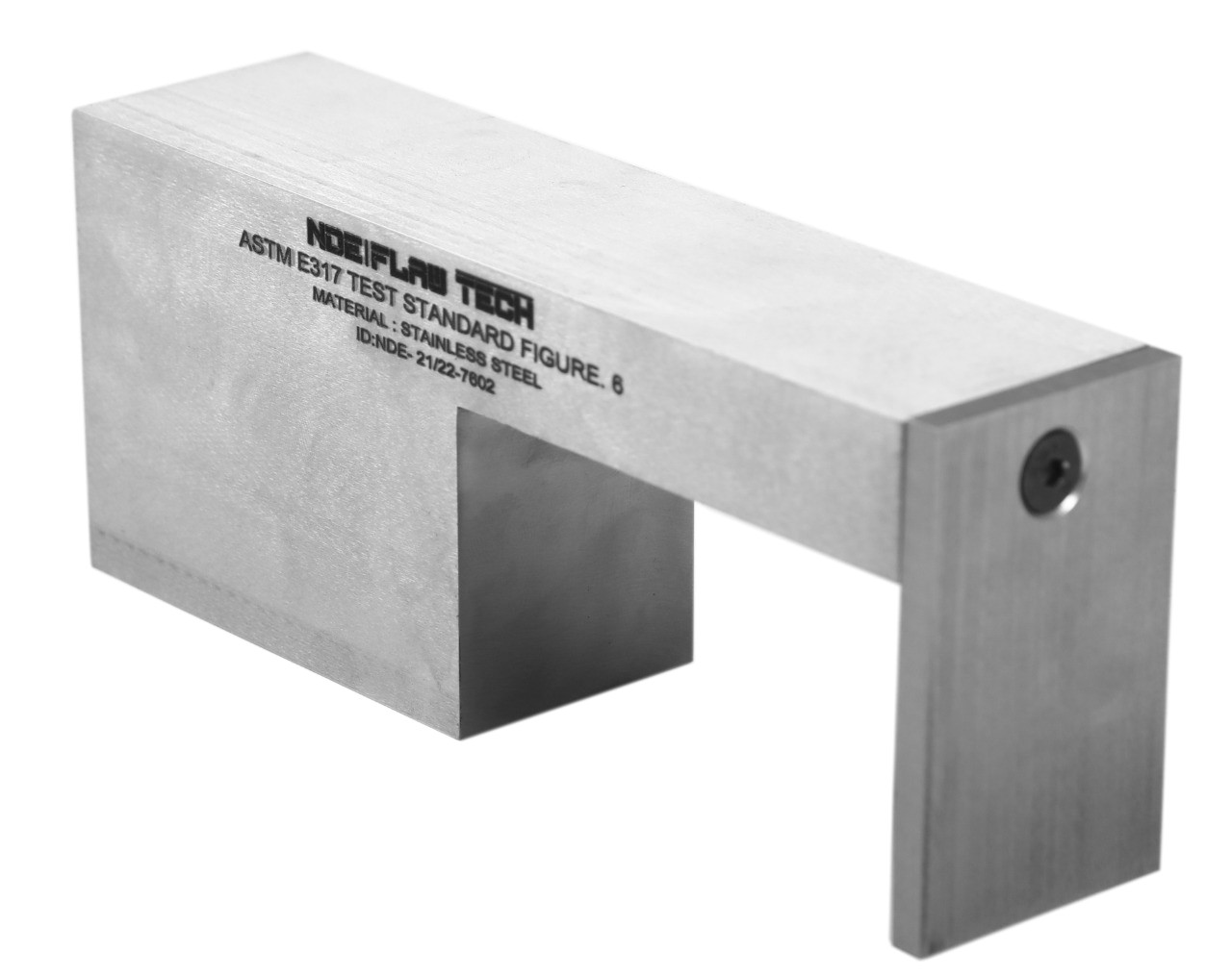
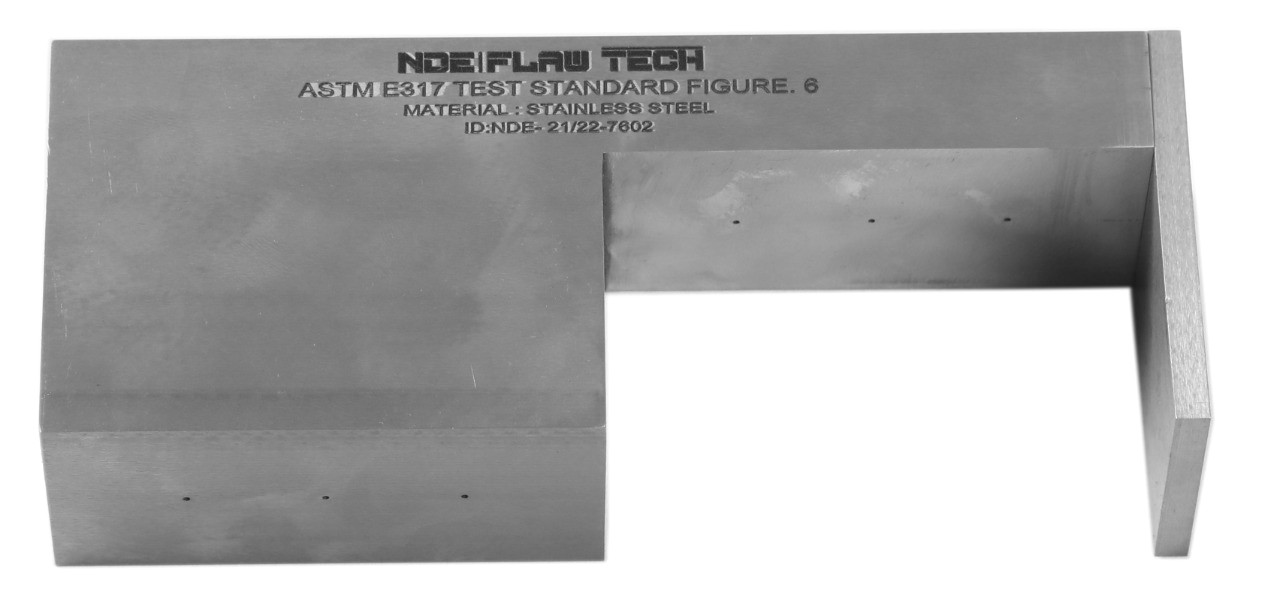
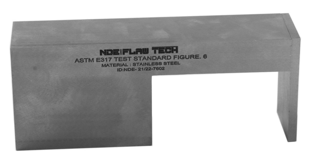
ASTM E317 Test Block Figure 6 (Inch Version) Special Alloy
ASTM E317 Test Block Figure 6 (Inch Version) Special Alloy ASTM E317 resolution block, Figure 6 is used for evaluating the resolution characteristics of ultrasonic pulse-echo systems. ASTM E317 Figure 6. Using this block, adjust the instrument controls to set the system sensitivity to the specified level without excessive loss of resolution. To obtain optimum sensitivity/resolution performance, adjustment of pulse length as well as one or more gain controls will frequently be necessary. If an immersion test, make certain that the search unit is positioned laterally for maximum hole-signal amplitude and aligned for interface perpendicularity. Except for interface peaking, no lower gain may be used thereafter, although higher may be required as described. Resolution, either entry or far surface, is determined as follows. Using the established sensitivity, reposition the search unit over each specified hole in turn to optimize the indication, again making certain that the interface signal is maximized by alignment of the search unit Geometry: Six Ø3/64" diameter flat-bottom holes. Dimensions: 2.00" (W) x 1.00/3.30" (T) x 8.00" (L) Inch Material: Special Alloy
ASTM E317 Test Block Figure 6 (Inch Version) 1018 Steel
ASTM E317 Test Block Figure 6 (Inch Version) 1018 Steel ASTM E317 resolution block, Figure 6 is used for evaluating the resolution characteristics of ultrasonic pulse-echo systems. ASTM E317 Figure 6. Using this block, adjust the instrument controls to set the system sensitivity to the specified level without excessive loss of resolution. To obtain optimum sensitivity/resolution performance, adjustment of pulse length as well as one or more gain controls will frequently be necessary. If an immersion test, make certain that the search unit is positioned laterally for maximum hole-signal amplitude and aligned for interface perpendicularity. Except for interface peaking, no lower gain may be used thereafter, although higher may be required as described. Resolution, either entry or far surface, is determined as follows. Using the established sensitivity, reposition the search unit over each specified hole in turn to optimize the indication, again making certain that the interface signal is maximized by alignment of the search unit Geometry: Six Ø3/64" diameter flat-bottom holes. Dimensions: 2.00" (W) x 1.00/3.30" (T) x 8.00" (L) Inch Material: 1018 Steel

ASTM E317 Test Block Figure 6 (Inch Version) STAINLESS STEEL 304
ASTM E317 Test Block Figure 6 (Inch Version) STAINLESS STEEL 304 ASTM E317 resolution block, Figure 6 is used for evaluating the resolution characteristics of ultrasonic pulse-echo systems. ASTM E317 Figure 6. Using this block, adjust the instrument controls to set the system sensitivity to the specified level without excessive loss of resolution. To obtain optimum sensitivity/resolution performance, adjustment of pulse length as well as one or more gain controls will frequently be necessary. If an immersion test, make certain that the search unit is positioned laterally for maximum hole-signal amplitude and aligned for interface perpendicularity. Except for interface peaking, no lower gain may be used thereafter, although higher may be required as described. Resolution, either entry or far surface, is determined as follows. Using the established sensitivity, reposition the search unit over each specified hole in turn to optimize the indication, again making certain that the interface signal is maximized by alignment of the search unit Geometry: Six Ø3/64" diameter flat-bottom holes. Dimensions: 2.00" (W) x 1.00/3.30" (T) x 8.00" (L) Inch Material: STAINLESS STEEL 304.
ASTM E317 Test Block Figure 6 (Inch Version) STAINLESS STEEL 316
ASTM E317 Test Block Figure 6 (Inch Version) STAINLESS STEEL 316 ASTM E317 resolution block, Figure 6 is used for evaluating the resolution characteristics of ultrasonic pulse-echo systems. ASTM E317 Figure 6. Using this block, adjust the instrument controls to set the system sensitivity to the specified level without excessive loss of resolution. To obtain optimum sensitivity/resolution performance, adjustment of pulse length as well as one or more gain controls will frequently be necessary. If an immersion test, make certain that the search unit is positioned laterally for maximum hole-signal amplitude and aligned for interface perpendicularity. Except for interface peaking, no lower gain may be used thereafter, although higher may be required as described. Resolution, either entry or far surface, is determined as follows. Using the established sensitivity, reposition the search unit over each specified hole in turn to optimize the indication, again making certain that the interface signal is maximized by alignment of the search unit Geometry: Six Ø3/64" diameter flat-bottom holes. Dimensions: 2.00" (W) x 1.00/3.30" (T) x 8.00" (L) Inch Material: STAINLESS STEEL 316.

ASTM E317 Test Block Figure 6 (Inch Version) TITANIUM
ASTM E317 Test Block Figure 6 (Inch Version) TITANIUM ASTM E317 resolution block, Figure 6 is used for evaluating the resolution characteristics of ultrasonic pulse-echo systems. ASTM E317 Figure 6. Using this block, adjust the instrument controls to set the system sensitivity to the specified level without excessive loss of resolution. To obtain optimum sensitivity/resolution performance, adjustment of pulse length as well as one or more gain controls will frequently be necessary. If an immersion test, make certain that the search unit is positioned laterally for maximum hole-signal amplitude and aligned for interface perpendicularity. Except for interface peaking, no lower gain may be used thereafter, although higher may be required as described. Resolution, either entry or far surface, is determined as follows. Using the established sensitivity, reposition the search unit over each specified hole in turn to optimize the indication, again making certain that the interface signal is maximized by alignment of the search unit Geometry: Six Ø3/64" diameter flat-bottom holes. Dimensions: 2.00" (W) x 1.00/3.30" (T) x 8.00" (L) Inch Material: TITANIUM.

ASTM E317 Test Block Figure 6 (Inch Version) ALUMINUM 7075-T6
ASTM E317 Test Block Figure 6 (Inch Version) ALUMINUM 7075-T6 ASTM E317 resolution block, Figure 6 is used for evaluating the resolution characteristics of ultrasonic pulse-echo systems. ASTM E317 Figure 6. Using this block, adjust the instrument controls to set the system sensitivity to the specified level without excessive loss of resolution. To obtain optimum sensitivity/resolution performance, adjustment of pulse length as well as one or more gain controls will frequently be necessary. If an immersion test, make certain that the search unit is positioned laterally for maximum hole-signal amplitude and aligned for interface perpendicularity. Except for interface peaking, no lower gain may be used thereafter, although higher may be required as described. Resolution, either entry or far surface, is determined as follows. Using the established sensitivity, reposition the search unit over each specified hole in turn to optimize the indication, again making certain that the interface signal is maximized by alignment of the search unit Geometry: Six Ø3/64" diameter flat-bottom holes. Dimensions: 2.00" (W) x 1.00/3.30" (T) x 8.00" (L) Inch Material: ALUMINUM 7075-T6

ASTM E317 Test Block Figure 6 (Inch Version) INCONEL 625
ASTM E317 Test Block Figure 6 (Inch Version) INCONEL 625 ASTM E317 resolution block, Figure 6 is used for evaluating the resolution characteristics of ultrasonic pulse-echo systems. ASTM E317 Figure 6. Using this block, adjust the instrument controls to set the system sensitivity to the specified level without excessive loss of resolution. To obtain optimum sensitivity/resolution performance, adjustment of pulse length as well as one or more gain controls will frequently be necessary. If an immersion test, make certain that the search unit is positioned laterally for maximum hole-signal amplitude and aligned for interface perpendicularity. Except for interface peaking, no lower gain may be used thereafter, although higher may be required as described. Resolution, either entry or far surface, is determined as follows. Using the established sensitivity, reposition the search unit over each specified hole in turn to optimize the indication, again making certain that the interface signal is maximized by alignment of the search unit Geometry: Six Ø3/64" diameter flat-bottom holes. Dimensions: 2.00" (W) x 1.00/3.30" (T) x 8.00" (L) Inch Material: INCONEL 625.
ASTM E317 Test Block Figure 6 (Inch Version) MONAL 800
ASTM E317 Test Block Figure 6 (Inch Version) MONAL 800 ASTM E317 resolution block, Figure 6 is used for evaluating the resolution characteristics of ultrasonic pulse-echo systems. ASTM E317 Figure 6. Using this block, adjust the instrument controls to set the system sensitivity to the specified level without excessive loss of resolution. To obtain optimum sensitivity/resolution performance, adjustment of pulse length as well as one or more gain controls will frequently be necessary. If an immersion test, make certain that the search unit is positioned laterally for maximum hole-signal amplitude and aligned for interface perpendicularity. Except for interface peaking, no lower gain may be used thereafter, although higher may be required as described. Resolution, either entry or far surface, is determined as follows. Using the established sensitivity, reposition the search unit over each specified hole in turn to optimize the indication, again making certain that the interface signal is maximized by alignment of the search unit Geometry: Six Ø3/64" diameter flat-bottom holes. Dimensions: 2.00" (W) x 1.00/3.30" (T) x 8.00" (L) Inch Material: MONAL 800.