
Phased Array IIW ISO 19675 Calibration Block (Inch Version) 1018 Steel
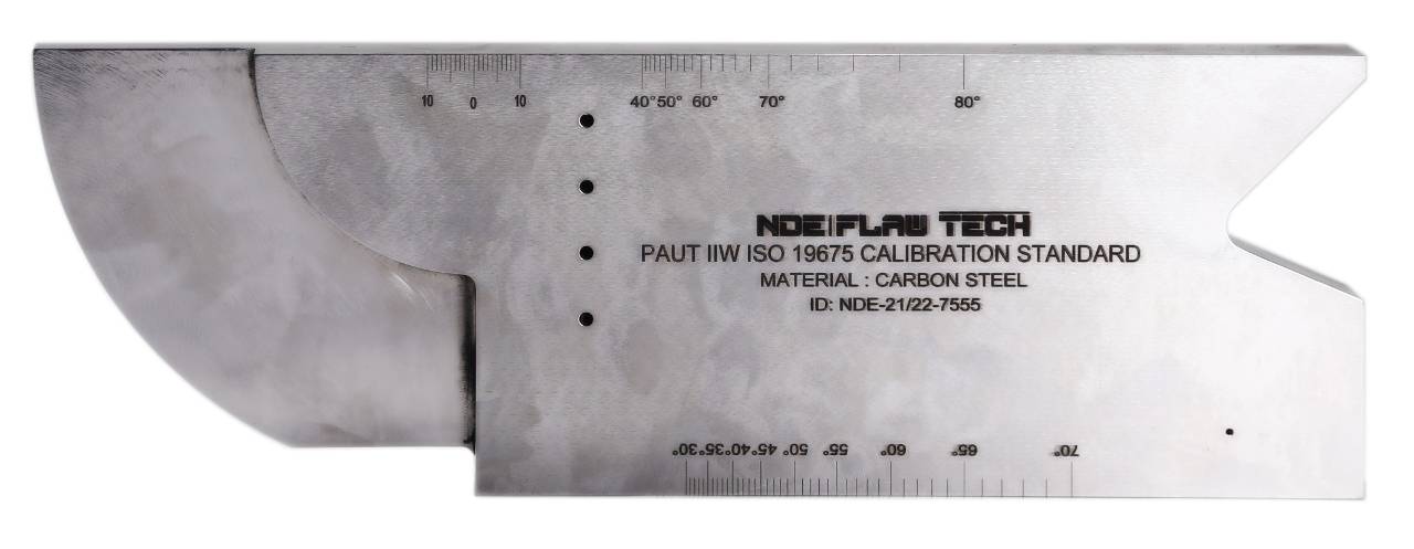
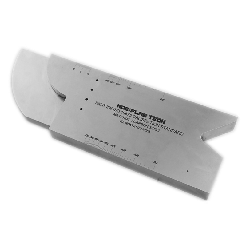
Phased Array IIW ISO 19675 Calibration Block (Inch Version) 1018 Steel At the first glance, the PAUT IIW block looks very similar to the former IIW conventional UT block, but it allows carrying out far more checking and calibration functions. Usages such as wedge delay, grating lobes assessment, active element assessment, sensitivity equalization, plotting check, element assignment, etc. Beam angle (angle beam probe), First the delay law for the angle beam being assessed shall be configured. Then the probe index shall be determined, by positioning the probe to maximize the echo response from the 100mm radius. Using a fine-tip marker, a line is drawn on the wedge where the center point of the 100mm radius meets the wedge. Then the probe is moved to maximize the response from either the uppermost or lowermost 3mm diameter side drilled hole. Read the value of the angle indicated on the scribed markings to the nearest 0.5° to determine the actual refracted angle can now be read. Element assignment - A B-scan of the delay law acquisitions is displayed and the amplitude and time of the back wall signal for each element in the array is observed. If the element #1 is nearest the end of the PAUT calibration block it will have the shortest arrival time in pulse-echo and all subsequent elements should display a monotonic increase in arrival time. B-scan from a 64 element probe with the response seen from the V surface of the block. The response from each element is slightly greater in time than its next adjacent element indicating correct assignment of elements. The PAUT IIW Block, made in accordance with ISO 19675 was designed by an international committee of NDT experts with the express purpose of creating a globally accepted, standardized block for Phased Array Ultrasonic calibrations. Before the development of this spec, there were no international standards describing a specific block for calibrating PAUT systems. Geometry: 1" wide x 4" tall x 12" long, with 4" and 2" radii Material: 1018 Steel

Phased Array IIW ISO 19675 Calibration Block (Inch Version) STAINLESS STEEL 304
Phased Array IIW ISO 19675 Calibration Block (Inch Version) STAINLESS STEEL 304 At the first glance, the PAUT IIW block looks very similar to the former IIW conventional UT block, but it allows carrying out far more checking and calibration functions. Usages such as wedge delay, grating lobes assessment, active element assessment, sensitivity equalization, plotting check, element assignment, etc. Beam angle (angle beam probe), First the delay law for the angle beam being assessed shall be configured. Then the probe index shall be determined, by positioning the probe to maximize the echo response from the 100mm radius. Using a fine-tip marker, a line is drawn on the wedge where the center point of the 100mm radius meets the wedge. Then the probe is moved to maximize the response from either the uppermost or lowermost 3mm diameter side drilled hole. Read the value of the angle indicated on the scribed markings to the nearest 0.5° to determine the actual refracted angle can now be read. Element assignment - A B-scan of the delay law acquisitions is displayed and the amplitude and time of the back wall signal for each element in the array is observed. If the element #1 is nearest the end of the PAUT calibration block it will have the shortest arrival time in pulse-echo and all subsequent elements should display a monotonic increase in arrival time. B-scan from a 64 element probe with the response seen from the V surface of the block. The response from each element is slightly greater in time than its next adjacent element indicating correct assignment of elements. The PAUT IIW Block, made in accordance with ISO 19675 was designed by an international committee of NDT experts with the express purpose of creating a globally accepted, standardized block for Phased Array Ultrasonic calibrations. Before the development of this spec, there were no international standards describing a specific block for calibrating PAUT systems. Geometry: 1" wide x 4" tall x 12" long, with 4" and 2" radii Material: STAINLESS STEEL 304

Phased Array IIW ISO 19675 Calibration Block (Inch Version) STAINLESS STEEL 316
Phased Array IIW ISO 19675 Calibration Block (Inch Version) STAINLESS STEEL 316 At the first glance, the PAUT IIW block looks very similar to the former IIW conventional UT block, but it allows carrying out far more checking and calibration functions. Usages such as wedge delay, grating lobes assessment, active element assessment, sensitivity equalization, plotting check, element assignment, etc. Beam angle (angle beam probe), First the delay law for the angle beam being assessed shall be configured. Then the probe index shall be determined, by positioning the probe to maximize the echo response from the 100mm radius. Using a fine-tip marker, a line is drawn on the wedge where the center point of the 100mm radius meets the wedge. Then the probe is moved to maximize the response from either the uppermost or lowermost 3mm diameter side drilled hole. Read the value of the angle indicated on the scribed markings to the nearest 0.5° to determine the actual refracted angle can now be read. Element assignment - A B-scan of the delay law acquisitions is displayed and the amplitude and time of the back wall signal for each element in the array is observed. If the element #1 is nearest the end of the PAUT calibration block it will have the shortest arrival time in pulse-echo and all subsequent elements should display a monotonic increase in arrival time. B-scan from a 64 element probe with the response seen from the V surface of the block. The response from each element is slightly greater in time than its next adjacent element indicating correct assignment of elements. The PAUT IIW Block, made in accordance with ISO 19675 was designed by an international committee of NDT experts with the express purpose of creating a globally accepted, standardized block for Phased Array Ultrasonic calibrations. Before the development of this spec, there were no international standards describing a specific block for calibrating PAUT systems. Geometry: 1" wide x 4" tall x 12" long, with 4" and 2" radii Material: STAINLESS STEEL 316
Phased Array IIW ISO 19675 Calibration Block (Inch Version) TITANIUM
Phased Array IIW ISO 19675 Calibration Block (Inch Version) TITANIUM At the first glance, the PAUT IIW block looks very similar to the former IIW conventional UT block, but it allows carrying out far more checking and calibration functions. Usages such as wedge delay, grating lobes assessment, active element assessment, sensitivity equalization, plotting check, element assignment, etc. Beam angle (angle beam probe), First the delay law for the angle beam being assessed shall be configured. Then the probe index shall be determined, by positioning the probe to maximize the echo response from the 100mm radius. Using a fine-tip marker, a line is drawn on the wedge where the center point of the 100mm radius meets the wedge. Then the probe is moved to maximize the response from either the uppermost or lowermost 3mm diameter side drilled hole. Read the value of the angle indicated on the scribed markings to the nearest 0.5° to determine the actual refracted angle can now be read. Element assignment - A B-scan of the delay law acquisitions is displayed and the amplitude and time of the back wall signal for each element in the array is observed. If the element #1 is nearest the end of the PAUT calibration block it will have the shortest arrival time in pulse-echo and all subsequent elements should display a monotonic increase in arrival time. B-scan from a 64 element probe with the response seen from the V surface of the block. The response from each element is slightly greater in time than its next adjacent element indicating correct assignment of elements. The PAUT IIW Block, made in accordance with ISO 19675 was designed by an international committee of NDT experts with the express purpose of creating a globally accepted, standardized block for Phased Array Ultrasonic calibrations. Before the development of this spec, there were no international standards describing a specific block for calibrating PAUT systems. Geometry: 1" wide x 4" tall x 12" long, with 4" and 2" radii Material: TITANIUM
Phased Array IIW ISO 19675 Calibration Block (Inch Version) INCONEL 625
Phased Array IIW ISO 19675 Calibration Block (Inch Version) INCONEL 625 At the first glance, the PAUT IIW block looks very similar to the former IIW conventional UT block, but it allows carrying out far more checking and calibration functions. Usages such as wedge delay, grating lobes assessment, active element assessment, sensitivity equalization, plotting check, element assignment, etc. Beam angle (angle beam probe), First the delay law for the angle beam being assessed shall be configured. Then the probe index shall be determined, by positioning the probe to maximize the echo response from the 100mm radius. Using a fine-tip marker, a line is drawn on the wedge where the center point of the 100mm radius meets the wedge. Then the probe is moved to maximize the response from either the uppermost or lowermost 3mm diameter side drilled hole. Read the value of the angle indicated on the scribed markings to the nearest 0.5° to determine the actual refracted angle can now be read. Element assignment - A B-scan of the delay law acquisitions is displayed and the amplitude and time of the back wall signal for each element in the array is observed. If the element #1 is nearest the end of the PAUT calibration block it will have the shortest arrival time in pulse-echo and all subsequent elements should display a monotonic increase in arrival time. B-scan from a 64 element probe with the response seen from the V surface of the block. The response from each element is slightly greater in time than its next adjacent element indicating correct assignment of elements. The PAUT IIW Block, made in accordance with ISO 19675 was designed by an international committee of NDT experts with the express purpose of creating a globally accepted, standardized block for Phased Array Ultrasonic calibrations. Before the development of this spec, there were no international standards describing a specific block for calibrating PAUT systems. Geometry: 1" wide x 4" tall x 12" long, with 4" and 2" radii Material: INCONEL 625

Phased Array IIW ISO 19675 Calibration Block (Inch Version) MONAL 800
Phased Array IIW ISO 19675 Calibration Block (Inch Version) MONAL 800 At the first glance, the PAUT IIW block looks very similar to the former IIW conventional UT block, but it allows carrying out far more checking and calibration functions. Usages such as wedge delay, grating lobes assessment, active element assessment, sensitivity equalization, plotting check, element assignment, etc. Beam angle (angle beam probe), First the delay law for the angle beam being assessed shall be configured. Then the probe index shall be determined, by positioning the probe to maximize the echo response from the 100mm radius. Using a fine-tip marker, a line is drawn on the wedge where the center point of the 100mm radius meets the wedge. Then the probe is moved to maximize the response from either the uppermost or lowermost 3mm diameter side drilled hole. Read the value of the angle indicated on the scribed markings to the nearest 0.5° to determine the actual refracted angle can now be read. Element assignment - A B-scan of the delay law acquisitions is displayed and the amplitude and time of the back wall signal for each element in the array is observed. If the element #1 is nearest the end of the PAUT calibration block it will have the shortest arrival time in pulse-echo and all subsequent elements should display a monotonic increase in arrival time. B-scan from a 64 element probe with the response seen from the V surface of the block. The response from each element is slightly greater in time than its next adjacent element indicating correct assignment of elements. The PAUT IIW Block, made in accordance with ISO 19675 was designed by an international committee of NDT experts with the express purpose of creating a globally accepted, standardized block for Phased Array Ultrasonic calibrations. Before the development of this spec, there were no international standards describing a specific block for calibrating PAUT systems. Geometry: 1" wide x 4" tall x 12" long, with 4" and 2" radii Material: MONAL 800