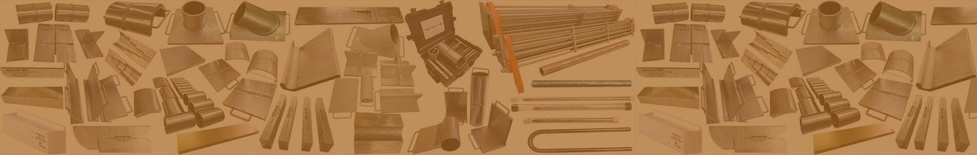
STANDARDIZED FLAWED SPECIMEN KITS FOR TRAINING, PERSONNEL QUALIFICATION, PROCEDURE AND EQUIPMENT DEVELOPMENT.
17.0. STANDARDIZED FLAW SPECIMEN KIT
We
are providing standardized flaw specimen kit for accept / reject level of flaws
as per individual standards like ASME, AWS, ISO/BS/EN. We are specialized of
manufacturing welded flaw specimen in accordance to standard. As per ASME
acceptance criteria we are manufacturing flaw specimen with accept level as
well as in reject level and providing report with photo document. Similarly we
manufacturing welded flaw specimen in accordance with AWS, ISO along with
report and photo document.
17.1. AMERICAN SOCIETY OF MECHANICAL ENGINEERS (ASME)
ASME
is one of the oldest standards-developing organizations in America. It produces
approximately 600 codes and standards covering many technical areas, such as
fasteners, plumbing fixtures, elevators, pipelines, and power plant systems and
components. ASME's standards are developed by committees of subject matter
experts using an open, consensus-based process. Many ASME standards are cited
by government agencies as tools to meet their regulatory objectives. ASME
standards are therefore voluntary, unless the standards have been incorporated
into a legally binding business contract or incorporated into regulations
enforced by an authority having jurisdiction, such as a federal, state, or
local government agency. ASME's standards are used in more than 100 countries
and have been translated into numerous languages.
17.1.1. ACCEPTANCE CRITERIA FOR ULTRASONIC:
Imperfections which produce
a response greater than 20% of the reference level shall be investigated to the
extent that the operator can determine the shape, identity, and location of all
such imperfections and evaluate them in terms of the acceptance standards given
in (a) and (b) below.
Indications characterized as cracks, lack of fusion, or
incomplete penetration is unacceptable regardless of other imperfections are
unacceptable. If the indications exceed the reference level amplitude and have
lengths which exceed:
·
1/4
in. (6 mm) for t up to 3/4 in. (19 mm);
·
1/3t
for t from 3/4 in. to 21/4 in. (19 mm to 57 mm); (3) 3/4 in. (19 mm) for t over
21/4 in. (57mm).
Where t is the thickness of the weld excluding any allowable reinforcement. For a butt weld joining two members having different thicknesses at the weld, t is the thinner of these two thicknesses. If a full penetration weld includes a fillet weld, the thickness of the throat of the fillet shall be included in t.
1. ASME B 16.34 – VALVES – ULTRASONIC TESTING ACCEPTANCE STANDARDS
Straight Beam Examination
Indications which are equal to or exceed that obtained from a 6.4 mm (0.25 in.) diameter flat bottomed hole in a calibration test piece of thickness equal to the defect depth are unacceptable.
Angle Beam Examination
Indications which are equal to or exceed those obtained from a 60 deg V-notch, 25 mm (1.0 in.) long and having a depth not greater than 5% of the nominal wall thickness in a test piece are unacceptable.
2. ASME B 31.1 – POWER PIPING – ULTRASONIC TESTING:
Welds that are shown by ultrasonic examination to have discontinuities that produce an indication greater than 20% of the reference level shall be investigated to the extent that ultrasonic examination personnel can determine their shape, identity, and location so that they may evaluate each discontinuity for acceptance in accordance with (B.1) and (B.2) below.
(B.1) Discontinuities evaluated as being cracks, lack of fusion, or incomplete penetration are unacceptable regardless of length.
(B.2) other discontinuities are unacceptable if the indication exceeds the reference level and their length exceeds the following:
(B.2.1) ¼” (6.0 mm) for t up to ¾” (19.0 mm).
(B.2.2) 1/3 t for t from ¾” (19.0 mm) to 2 ¼ “ (57.0 mm).
(B.2.3) ¾”. (19.0 mm) for t over 2¼” (57.0 mm)
Where t is the thickness of the weld being examined. If the weld joins two members having different thicknesses at the weld, t is the thinner of these two thicknesses.
3. ASME B31.3 PROCESS PIPING – ULTRASONIC TESTING
Inspection of Weld Joints carried as per ASME Section V , Article 4 Pipe and Tubin
I) Pipe and tubing, required or selected in accordance with Table K305.1.2 to undergo ultrasonic examination, shall pass a 100% examination for longitudinal defects in accordance with ASTM E213 Ultrasonic Testing of Metal Pipe and Tubing. Longitudinal (axial) reference notches shall be introduced on the outer and inner surfaces of the calibration (reference) standard in accordance with Fig. 3(c) of ASTM E213 to a depth not greater than the larger of 0.1 mm (0.004 in.) or 4% of specimen thickness and a length not more than 10 times the notch depth.
II) Acceptance Criteria. Any indication greater than that produced by the calibration notch representation Welds over 6mm thick can be ultrasonically tested in reference with procedure given in ASME Sec V article 4. Indications shall be sized using the applicable technique(s) provided in the written procedure for the examination method. Indications shall be evaluated for acceptance as follows
III) All indications characterized as cracks, lack of fusion, or incomplete penetration are unacceptable regardless of length.
Where “t” is the thickness of the weld excluding any allowable reinforcement. For a butt weld joining two members having different thicknesses at the weld, t is the thinner of these two thicknesses. If a full penetration weld includes a fillet weld, the thickness of the throat of the fillet shall be included in t .
4. API 1104 WELDING OF PIPELINES & RELATED FACILITIES – ULTRASONIC TESTING – ACCEPTANCE LEVEL
Acceptance Standards 9.6.2.1 Indications determined to be cracks (C) shall be considered
Linear surface (LS) indications (other than cracks) interpreted to be open to the I.D. or O.D. surface shall be considered defects should any of the following conditions exist:
1. The aggregate length of LS indications in any continuous 12”(300-mm) length of weld exceeds 1”. (25 mm).
2. The aggregate length of LS Indications exceeds 8% of the weld
Linear buried (LB) indications (other than cracks) interpreted to be subsurface within the weld and not I.D. or O.D. surface-connected shall be considered defects should any of the following conditions exist:
1. The aggregate length of LB indications in any continuous 12”(300-mm) length of weld exceeds 2” (50 mm).
2. The aggregate length of LB indications exceeds 8% of the weld
Transverse (T) indications (other than cracks) shall be considered volumetric and evaluated using the criteria for volumetric indications. The letter T shall be used to designate all reported transverse indications.
1. Volumetric cluster (VC) indications shall be considered defects when the maximum dimension of VC indications exceeds 1/2 “ (13 mm).
Volumetric individual (VI) indications shall be considered defects when the maximum dimension of VI indications exceeds 1/4 “ (6 mm) in both width and
2. Volumetric root (VR) indications interpreted to be open to the D. surface shall be considered defects should any of the following conditions exist:
1. The maximum dimension of VR indications exceeds 1/4“ (6mm).
2. The total length of VR indications exceeds 1/2 “ (13 mm) in any continuous 12” (300 ).
Any accumulation of relevant indications (AR) shall be considered a defect when any of the following conditions exist:
1. The aggregate length of indications above the evaluation level exceeds 2 “(50 mm) in any 12” (300mm) length
2. The aggregate length of indications above evaluation level exceeds 8% of the weld
17.1.2. ACCEPTANCE CRITERIA FOR MAGNETIC PARTICLE
TESTING (MPT):
ASME B31.1, Power Piping Acceptance Standards. The
following relevant indications are unacceptable:
·
Any
cracks or linear indications.
·
Rounded
indications with dimensions greater than 3/16 in. (5.0 mm)
·
Four
or more rounded indications in a line separated by 1/16 in. (2.0 mm) or less,
edge to edge.
·
Ten
or more rounded indications in any 6 sq. in of surface with the major dimension
of this area not to exceed 6 in (150 mm) with the area taken in the most unfavorable
location relative to the indications being evaluated
ASME
Boiler and Pressure Vessel Code, Sec. VIII Div.1 Pressure Vessels Acceptance
Standards. All surfaces to be examined shall be free of:
·
Relevant
linear indications
·
Relevant
rounded indications greater than 3/16 in.
· Four or more relevant rounded indications in a line separated by 1/16 in. or less, edge to edge.
17.2. AMERICAN WELDING SOCIETY:
The American
Welding Society (AWS) was founded in 1919 as a non-profit organization to advance the science, technology and application of welding and
allied joining and cutting processes,
including brazing, soldering and thermal spraying.
AWS publishes codes on multiple aspects of welding and
materials joining. The code books are assigned specific letters and numbers for
easy reference, and many welders will refer to a specific code letter/number
combination when referring to the code book. Different welding methodologies,
inspection methods, and metals are published under different codes. For
example, AWS B1.11 explains how to visually examine welds; AWS B2.1-1-004
explains welding carbon steel of thickness range of 18
through 10 gauge with semiautomatic metal gas arc welding;
and AWS C2.20/C2.20M explains metalized zinc cathodic protection systems. Some
codes also describe the standards used by AWS to certify welders, inspectors,
and welding educators. All codes are available in hard copy, and in recent
years AWS has started to make most codes available online. A very influential
AWS code is AWS D1.1, which covers all general requirements for structural
welding. This code has been adopted by ANSI as a National
Standard in the United States.
17.2.1. ACCEPTANCE CRITERIA FOR ULTRASONIC TESTING (UT):
17.2.2. ACCEPTANCE CRITERIA FOR VISUAL TESTING (VT), MAGNETIC
PARTICLE TESTING (MPT), LIQUID PENETRANT TESTING (LPT):
17.3. ISO/ EN/ BS:
17.3.1. ACCEPTANCE CRITERIA FOR ULTRASONIC TESTING (UT):
17.3.2. ACCEPTANCE CRITERIA FOR LIQUID PENETRANT TESTING (LPT):
17.3.3. ACCEPTANCE CRITERIA FOR MAGNETIC PARTICLE TESTING (MPT):
18.0. CASTING and FORGING DEFECTIVE SAMPLE: